Facebook
 Google
 GitHub
 Linkedin
Low Loss HighPower Thyristors for Industrial Applications
This article introduces ABB's development of the Phase Control Thyristor for HVDC and discusses its design concept and the device performance.
Though one of the oldest semiconductor devices ever, the thyristor maintains a significant market share. This is because of its attractive price-performance ratio mainly due to the lowest ON-state losses and the easiest processing from existing gated switches. ABB has developed a new range of thyristors offering very low ON-state voltage drop, low leakage current and high blocking stability without compromising the AC voltage waveform. The safe operating temperature is up to Tjmax = 115°C with sufficient margin assuring a reliable operation in demanding industrial applications like static VAR compensators, cyclo converters or hydro-electric applications.
A Phase Control Thyristor (PCT) can be found in power supplies, motor drives, induction heating, power quality systems, hydro pumping and other applications. It is the main semiconductor switch, when the lowest ON-State voltage drop is a must. It is therefore not surprising that the development effort of high-power PCTs proceeds towards the devices with even lower losses for given blocking stability.
Following the successful development of the PCT for High-Voltage Direct Current transmission (HVDC) [1, 2], ABB introduces the same design concept also to industrial applications. Since the new concept provides significantly lower ON-state voltage drop VT and leakage current, while maintaining the original blocking capability, it is suitable for the operation at temperatures higher than that of the HVDC Classic systems from ABB. The operation up to Tjmax = 115°C and its impact on device parameters relevant for the industry is demonstrated below for the PCT in the package with 100 mm pole piece diameter (see Fig.1). The most relevant parameters to be improved from a customers´ perspective are
- ON-state voltage drop VT – reverse recovery charge Qrr (losses),
- AC blocking capability up to the full repetitive peak blocking voltages VDRM and VRRM,
- Surge current ITSM (overload ruggedness).

Figure 1: New 8.5 kV PCT with 100 mm pole piece for industrial applications.
There are generally three ways of increasing the output current of an inverter/converter:
- Reduction of overall (ON-state and switching) losses,
- Reduction of thermal resistance of the package,
- Increase of the maximal junction operation temperature Tjmax.
In our new device concept, the first improvement option has been chosen. This has been supplemented by the reduction of leakage current, which has brought an improved blocking ruggedness.
Design Concept
The new device concept is based on thinning the P-type anode and P-base layers in the active area, while leaving their original thickness at junction termination (JT) in order to maintain the original blocking capability. The example for double-side negative bevel used in the device under discussion is shown in Figure 2.
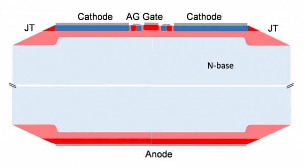
Figure 2: New design concept. P-type layers are red and pink, N-type layers blue and light blue
In the bulk, where the N-base is thicker than at the JT, the leakage current caused by the punch-through effect is minimized. At the periphery, the punch-through effect remains in its original magnitude. However, as the bulk represents about 90 % of the total area, the total leakage current is greatly reduced both under forward and reverse blocking. Using this concept, the total device thickness can be slightly lowered in order to achieve a lower VT. Thanks to the significantly lowered leakage current, there is no loss of original breakdown voltage, if the thinning is carefully optimized.
Device performance
Fig.3 shows the temperature dependence of leakage current measured using half-wave sine voltage at the frequency of 6.25 Hz up to the value of non-repetitive peak off-state blocking voltage in both forward and reverse direction. The measured magnitudes stay well within the original specification of the forward and leakage currents IDRM and IRRM for 8.0 kV and T = 115°C even when measured up to T = 125°C at the 8.5 kV level of the VRSM and VDSM rating. Well acceptable spread between individual parts is indicated by the error bars. All this is possible thanks to the massive reduction of the leakage current using the device concept shown in Figure2.
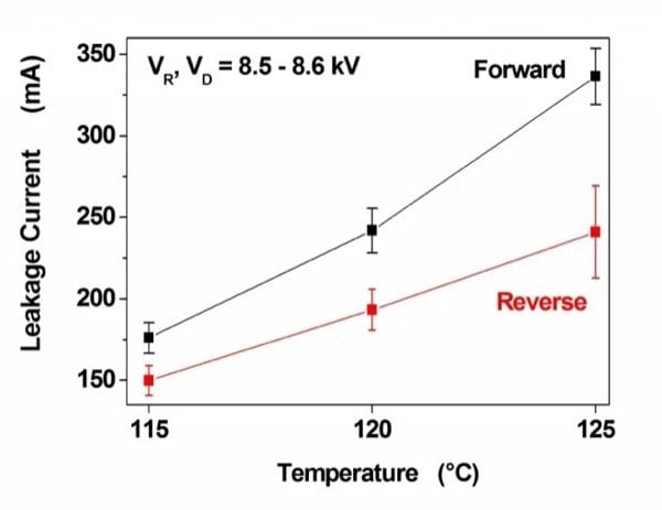
Figure 3: Leakage current vs. operation temperature from periodic blocking voltage test using half sine wave of VR and VD ≥ 8.5 kV (tp = 10 ms, f = 6.25 Hz).
Figure 4 shows the periodic blocking voltage test according to standards for thyristors subjected to periodic voltage stress. The half sine with tp = 10 ms is applied with the amplitude equal to the so-called working voltage VRWM. In this particular example, VRWM amounts to two thirds of the repetitive peak reverse blocking voltage VRRM. The amplitude of VRRM is then applied only for a shorter period of about 250 µs. An analogous example could be shown for the forward blocking region. In agreement with existing literature for thyristors in the HVDC or industry, manufacturers typically apply VRWM (VDWM) between 60 and 80% of VRRM (VDRM) [3].
However, the demanding industrial applications require the capability of VRWM = VRRM and VDWM = VDRM without compromising the amplitude of the half sine wave. Figs.5a) and b) show that our PCTs can satisfy this demand for the frequency of 50 Hz and for the lower frequency of 6.25 Hz they can go even beyond this limit. Since the leakage current at T = 125°C is still relatively high at such high voltages, we limit the maximal operation temperature to T = 115°C in order to keep a sufficient margin, which guarantees the long term reliability. We will see below, that from the viewpoint of maximizing the output current of a converter, this restriction is well compensated by the lowered ON-state voltage drop VT.
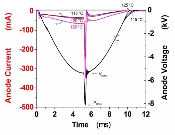
Figure 4: Blocking voltage and current at different operation temperatures during periodic blocking voltage test using half sine wave of VRWM = 5.7 kV superimposed by surge voltage up to VRRM = 8 kV.
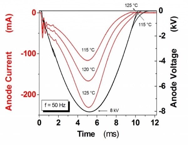
Figure 5a: Blocking voltage and current at different operation temperatures during periodic blocking voltage test using half sine wave up to VRRM = 8.0 kV. tp = 10 ms, f = 50 Hz.
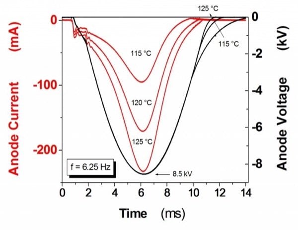
Figure 5b: Blocking voltage and current at different operation temperatures during periodic blocking voltage test using half sine wave up to VRSM = 8.5 kV. tp = 10 ms, f = 6.25 Hz.
Fig.6 shows the improvement of the ON-state voltage drop between the current and new generation of industrial PCTs with 100 mm pole piece at T = 115°C. The grey curve illustrates the range of typical specifications of reverse recovery charge Qrr for industrial applications, which can be found between 3000 – 8000 µAs. In the whole range of this Qrr, the VT of the new PCT is reduced by about 300 mV.
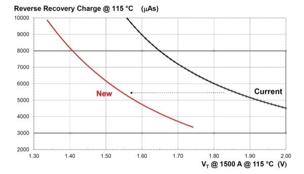
Figure 6: Technology curve Qrr – VT for the existing and new 8.5 kV PCT.
Figure 7 shows the temperature dependence of the Qrr – VT relation for the new devices and two other competitors. It implies that our new PCT belongs to the state-of-the-art. It also shows that the magnitude of VT is independent of temperature at IT = 1.5 kA and higher, which supports good thermal stability at continuous operation and high value of surge current ITSM as well.

Figure 7: Reverse recovery charge Qrr vs. ON-state voltage drop VT of 8.5 kV PCTs with 100 mm pole piece for operation temperatures 115, 120 and 125°C. Qrr of all devices was tested using IT = 2 kA, di/dt = -1.5 A/µs, VR = -200 V.
Conclusions
The surge current of the new device was measured at T = 125°C for a half sine pulse length of 10 ms with subsequently applied half sine forward voltage VD = 5.1 kV (60% of VRRM) with the delay of 1.5 ms after the surge. The last pass value was achieved at ITSM ≈ 29 kA, which corresponds to a typical capability expected from the PCTs with 100 mm pole piece. A similar value has been obtained from the triple pulse surge current test without re-applied voltage. The good ITSM ratings reflect the reduced ON-state losses of the new device, the effect of which is stronger than that of the reduced thermal capacity due to thinner starting silicon wafer.
The new thyristor of 8.5 kV class with 100 mm pole piece has been developed for industrial applications. This device shows a 300 mV lower voltage drop compared to the previous generation. The significant lowering of leakage current provided by the new design concept enabled us to permit the maximal voltage amplitude for 50 Hz half sine wave up to the full forward and reverse repetitive blocking voltage levels VDRM and VRRM up to 115°C.
About the Authors
Jan Vobecký works as a Senior Principal Research and Development Engineer at ABB Switzerland Ltd. - Semiconductors, Lenzburg, Switzerland. He earned his Master's of Science in Electrotechnology as well as his PhD at Czech Technical University in Prague, Czechia where he focused on Semiconductor devices, ICs and Microelectronics principles, design, processing, characterization and testing. Furthermore, he was also into classical, quantum physics and electric circuit theory. He also earned numerous certifications in Business Processes and Tools and have filed Patents on various semiconductor devices.
Karlheinz Stiegler works as the Senior Process Engineer at ABB Switzerland since April 2013 where he is responsible for the wet chemical processes, diffusion and low-temperature compounds. He has accomplished three publications, 3 patents and has achieved 4 courses throughout his career. He earned his Engineering Diploma in Microsystems Technology at The Regensburg University of Applied Sciences located in Germany.
Florian Weber works at ABB Switzerland as a Senior Technical Customer Support since June 2014 responsible for offering technical customer support for design-in and maintenance phases, product applications as well as risk assessment for deviations. He earned his Engineering Diploma in Electrical Engineering at the FH Aachen.
Roger Siegrist works at ABB Switzerland, a technology leader that is driving the digital transformation of industries. With a history of innovation spanning more than 130 years, ABB has four customer-focused, globally leading businesses: Electrification, Industrial Automation, Motion, and Robotics & Discrete Automation, supported by the ABB Ability™ digital platform. ABB operates in more than 100 countries with about 147,000 employees.
References
- J. Vobecky, V. Botan. K. Stiegler, U. Meier, M. Bellini, „A Novel Ultra-Low Loss Four Inch Thyristor for UHVDC”, Proceedings of the 27th International Symposium on Power Semiconductor Devices & ICs 2015, Hong Kong, pp. 413 – 416.
- J. Vobecky, V. Botan. K. Stiegler, M. Bellini, U. Meier, „New Low Loss Thyristor for HVDC Transmission”, Proceedings PCIM Europe 2015, Nuremberg, pp. 885 – 890.
- M. Schenk, J. Przybilla, U. Kellner-Werdehausen, R. Barthelmess, J. Dorn, G. Sachs, M. Uder, S. Völkel, “State of the Art of Bipolar Semiconductors for Very High Power Applications”, Proceedings PCIM Europe 2015, Nuremberg, pp. 930 – 937.