Facebook
 Google
 GitHub
 Linkedin
Bourns Expands Its Line of Wirewound Chip Inductors
The new units feature ferrite cores and offer high Q values, high self-resonant frequencies, and low DC resistance.
The members of the miniature-sized CWF1610 and the CWF2414 series are the latest additions to Bourns’ wide array of wirewound chip inductors.

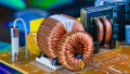
The CWF series of Chip Inductors. Image courtesy of Bourns
There are nine members of the CWF1610 series and seven members of the CWF2414 series. Both series feature ferrite cores, enameled copper wire, a tin terminal finish, and a moisture sensitivity level of 1. Also for both series, available induces range from 1.0 to 22µH with a 10% tolerance.
The saturation current (ISAT) is defined as the current at which the inductance value begins to drop. For both series of inductors, the rated inductance drops 20% at ISAT.
The CWF1610 Series
Complete information is found on the datasheet, the specifications feature ranges of:
- ISAT (typ): 200 to 860mA
- IRMS (typ): 200 to 700mA
- Q: either 14 or 16
- DC resistance (±30%): 0.32 to 3.61Ω
- Self resonant frequency (typ): 390 to 24 MHz
The CWF2414 Series
Specifications for this series are as below. The reader is referred to the datasheet for a complete compendium.
- ISAT (typ): 240 to 1100mA
- IRMS (typ): 340 to 1300mA
- Q: either 13, 14 or 15
- DC resistance (±30%): 0.13 to 1.76Ω
- Self resonant frequency (typ): 208 to 20 MHz
The Value Proposition for Wirewound Construction
Wirewound inductors feature thicker construction around their cores than do devices based on either multilayer technology or on film technology. This makes for lower DC resistances, and also for higher Q values, with the members of the two new series featuring Q values ranging from 13 to 16.
What is Meant by an Inductor’s Q?
An ideal inductor is an imaginary construct that offers inductive resistance, but no DC resistance. Q actually stands for quality factor. It can be defined as the ratio, at a given frequency, of an inductor’s inductive resistance to its DC resistance. The higher the Q, the closer the inductor is to an ideal inductor.
What is an Inductor’s Self Resonant Frequency?
Every inductor, to some extent, has its own parasitic capacitance. In the case of a wirewound inductor, that capacitance is caused by the proximity of the individual turns of the device’s coils to adjacent coils on either side. The inductance and parasitic capacitance form an LC circuit. The frequency at which the LC circuit resonates, where it offers high impedance, is called the resonant frequency.
Members of the CWF1610 and the CWF2414 series feature high self-resonant frequencies, which infers low distributed capacitance and results in maintained inductive characteristics over a wide frequency span.
Applications
The CWF1610 and CWF2414 are aimed at applications involving RF signal processing, DC power lines, decoupling, resonant circuits and noise filters. OEM products that will benefit include:
- Tablets
- Set-top boxes
- Cable modems
- Hard disk drives
- Audio headsets
- Mobile electronic devices
Physical Considerations
- Members of both series of wirewound chip resistors operate over a -40 to +125 °C temperature range
- The CWF1610 series measure 1.6 x 1 x 1 mm
- The CWF2414 series measure 2.2 x 1.4 x 1.3 mm
Environmental Characteristics
- RoHS compliant as per RoHS Directive 2015/863, Mar 31, 2015 and Annex.
- Halogen free as per Bourns’ specification