Facebook
 Google
 GitHub
 Linkedin
Allegro Debuts a 3-Phase Gate Driver IC Purposed to Reduce EV Noise Levels
The new unit is aimed at sensorless, brushless DC (BLDC) motors operating over a 5V to 50V voltage range.
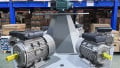
Allegro’s A89307 features and an integrated field-oriented control (FOC) algorithm that serves to drive continuous sinusoidal current to the load. The results are dramatic reductions in noise and vibration, as well as more driving miles per battery charge.

Image courtesy of Allegro
The Heightened Expectations of EV Owners
EV owners have a low tolerance for noise, and vehicle manufacturers, as well as their suppliers, have taken note. Here’s what Steve Lutz, Product Line Director for Motor Drivers at Allegro, has to say about it.
“By design, EV and hybrid vehicles are quieter than traditional models with internal combustion engines—especially when they’re stopped—and drivers are becoming increasingly sensitive to noise created by components such as cooling fans.” He goes on to say that, “The A89307’s hardware-based algorithm makes it easier for designers to reduce fan noise while improving cooling performance and increasing miles per charge. That’s good for drivers, and good for the environment.”
Features
The A89307 offers constant torque and constant power modes in addition to modes for constant speed and open-loop operation. The unit also optimizes motor startup from standstill, as well as from windmill or reverse windmill conditions.
The driver features a fully programmable closed-loop speed control mode where the customer can program the PWM-to-speed relationship to match an external electronic control unit (ECU). There is also an open-loop PWM mode available. This flexibility renders the driver readily compatible with a wide gamut of OEM interfaces.
The driver offers a configurable current limit and lock detection which serves to reduce motor heating. In the event of a failure of a MOSFET under the A89307’s control, the driver’s short-circuit protection (OCP) serves to protect the power supply and the PCB from an otherwise all too possible fire.
The A89307 offers an I2C interface for setting the motor’s rated voltage, current, speed, resistance, and startup profiles. The interface is also used for speed control, and speed readback. And is also used to affect on and off control.
Speed Control Details
Speed demand is provided via the SPD pin, as illustrated on the left side of the diagram below.

Functional block diagram of the A89307. Image courtesy of datasheet
The three separate speed control modes are the PWM, ANALOG and CLOCK Modes, selectable through the EEPROM.
- PWM MODE. Motor speed is controlled by the PWM duty cycle received at the SPD pin. The user chooses between open-loop and closed-loop.
- ANALOG MODE. Always closed-loop, with a higher frequency on the SPD pin causing a higher motor speed.
- CLOCK MODE. Also always closed loop, the input here, too, can come from the SPD pin. Alternatively, using either the DIR or the BRAKE terminal allows for simultaneous use of I2C inputs.
Applications
- Battery Cooling Fan
- HVAC Fan
- Traction inverter Cooling Systems
Physical Considerations
- The A89307 is available in a 28 lead wettable flank QFN package measuring 5mm x 5mm
- The driver operates over a temperature range of -40°C to 125°C
Regulatory
- AEC-Q100 qualified
Environmental
- RoHS compliant