Facebook
 Google
 GitHub
 Linkedin
Powering Drone Flight
A closer look at the rotor power and control architecture that gives flight to a drone.
Drone technologies continue to expand rapidly for military, commercial, law enforcement and consumer use cases. Drones, also referred to as UAVs (Unmanned Arial Vehicles), are unmanned aircraft or ships guided either remotely, or in some cases, autonomously.
Drones on the Rise
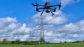
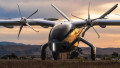
There are several different drone types suited to a range of different applications. Multi-rotor drones tend to be the least expensive with shorter ranges and payload capacities suitable for consumer video, photography and surveying applications. For more advanced payload and range capabilities, such as cargo delivery or military applications, Fixed Wing or Fixed-Wing Hybrids might be a better choice, but often come with a higher price tag.
Multi-rotor drone. Image used courtesy of DroneUp
A Rapidly Expanding Drone Market
Drones are attracting interest from investors and businesses. Total venture and IPO investments in the drone industry were ~ $7 billion in 2021, up from $2.4 billion in 2020. Earlier this year, Walmart announced it was expanding its drone delivery operations to 4 million households in six states. In partnership with DroneUp, LLC, Walmart plans to deliver more than 1 million packages, weighing up to 10 pounds each, to customers in Arizona, Arkansas, Florida, Texas, Utah and Virginia. Delivery times are targeted to be less than 30 minutes. Walmart is not alone as FedEx, Amazon and UPS are all exploring their own drone-based delivery services.
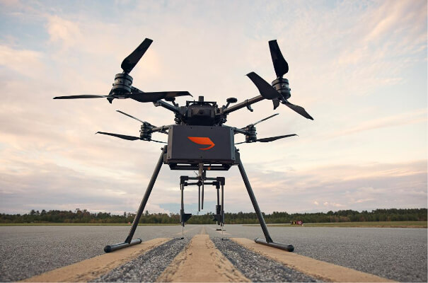
The Control Architecture of a Drone
To better understand the control and power electronics behind a quad-rotor drone, like those used in Walmart’s operations, we can take a look at the quadcopter drone reference design from NXP Semiconductors.

Drone quad motor control bock diagram. Image used courtesy of NXP
In a typical drone flight control system, the hand-held flight controller communicates commands from the pilot to the drone via radio. On the drone, the Flight Controller board receives these commands along with inputs from the Inertial Measurement Unit (IMU). The IMU provides velocity and orientation information from the internal accelerometer, gyroscope and other sensors needed for stable flight. The flight controller processes these inputs and sends commands to a separate Electronic Speed Controller (ESC) that is responsible for controlling pull, or speed, of each of the rotors. In a typical design each rotor will have a dedicated ESC board, but in the NXP design a single ESC board controls all four rotors using a Kinetis KV4x, ARM Cortex-M4 MCU. Further integration is possible by combing the Flight Controller and ESC boards into a single board using a higher performance MCU to control all drone functions.
Powering the Rotors
Each of the drone’s four rotors is powered by a 3-phase Brushless DC Motor (BLDC). A half-bridge inverter powers each of the BLDCs three phases and is controlled by the ESC MCU through a MC34GD3000 MOSFET gate pre-driver (x4). Each GD3000 generates all the inverter gate drive signals for a single BLDC. The inverters are constructed with N-type MOSFETS (PSMN4R2-30MLD), 24 total (6 per motor) across the full ESC board.

MC34GD3000 drives three phases of BLDC. Image used courtesy of NXP
Each inverter is powered by 12 V that can be supplied by an appropriate rechargeable battery. In selecting the right battery consideration should be given to weight, capacity and cost.

BLDC inverters powered by 12 V from battery. Image used courtesy of NXP
The 3.3 V supply rail for the ESC active components (MCU and Gate Drivers) is generated from the 12 V battery through a 5 V output R-78E5.0-0.5 buck converter followed by a MC33269DT-3.3G linear regulator.

Generating 3.3V for the ESC board active components. Image used courtesy NXP
Maintaining Rotor Speed
The ESC receives PWM-encoded (pulse-length or duty cycle) speed commands from the flight controller. Its MCU then implements a sophisticated six-step BLDC motor-control algorithm, incorporating current and voltage inputs from the inverter to ensure proper rotor speed is maintained.