Facebook
 Google
 GitHub
 Linkedin
Cost Optimization of Wireless Power Transmission Systems
Advantages of wireless power transmission systems in comparison to standard plug contacts are easily identified. Power transmitters, as well as power receivers,
Advantages of wireless power transmission systems in comparison to standard plug contacts are easily identified. Power transmitters, as well as power receivers, can be hermetically sealed, which simplifies the housing design a lot. There are no high-maintenance and malfunction-prone contacts needed and leaks in the contact area are largely excluded.
In the medical technology environment, this makes cleaning systems much easier. The energy can be transmitted by two plastic surfaces, which can be easily cleaned with any cleaning agents. Thermal sterilization is also no problem. There is also the possibility to load or supply medical implants without transcutaneous leads.
New Markets for Wireless Power Transmission Systems
In addition, there are many new markets to be tapped. For example, it is now possible to transfer not only data but also higher powers into closed or encapsulated systems and recharge a battery there. By removing the need for conductive connections, there is no contact spark, which means that wireless transmission systems are also increasingly important in explosion-protected environments.
However, if the advantages listed above provide little-added value for the specific product and if only the much-cited aspect of increased comfort can be identified, there is also the question of additional costs. But is it right to assume that a wireless transmission system is significantly more expensive than a plug-in connector?
In many cases, the component costs of a conventional plug-in connector are lower compared to the wireless transmission system. Factoring in failure and repair costs due to defective plug-in contacts results in an improved balance in favor of the wireless solution, but only the consistent optimization of the entire system concept proves that the use of a wireless system can even reduce the overall costs.
Inductive Energy Transmission System Functionality
But first a quick overview of the functionality of the inductive energy transmission systems, which are mainly in use. The energy transmission occurs via an alternating magnetic field from a transmitting coil to a receiving coil.

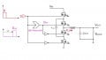
Figure 1: Wireless transmission system.
In a simplified form, a DC voltage is converted by a power amplifier, in image 1 shown as a half-bridge, into a rectangular high-frequency alternating voltage which feeds a transmitter resonant circuit. This resonant circuit consists of the most basic version of a resonant capacitor Ct and a transmitting coil Lt.
In accordance with the often controllable switching frequency of the input voltage, a current flow in the resonant circuit, which generates an alternating magnetic field in the near field of the coil Lt. This magnetic field causes an alternating current in the second, magnetically coupled coil Lr, which is supplied to a consumer after mostly active rectification. The additional resonance capacitor Cr improves efficiency.
Output voltage and/or output current are regulated by adjusting the switching frequency. In simplified terms, a high output power requires a large magnetic field and thus a large transmitter-side current. This means that the mostly digital control circuit selects a switching frequency close to the resonance frequency. On the other hand, with low output power, only a small magnetic field and thus a small transmission current is necessary. The controller chooses a switching frequency that is significantly different from the resonance frequency.
As mentioned above, the initial impression usually suggests that the wireless transmission system or, more generally, wireless power management must be significantly more expensive than a plug-in connector. But this comparison frequently ignores the fact that a wireless transmission system offers far more functionality than a plug-in connector. For example, the system provides:
- Galvanic isolation between transmitter and receiver
- Measurement and monitoring of input voltage (OVP, UVP), limitation of input power
- Measurement and monitoring of output voltage, limitation of output power
- Control of the output value. charging algorithm (CC/CV for LiIon) can be provided.
- Winding ratio can be adjusted. With a fixed input voltage many different output voltages are possible
- Operation largely free of wear and tear
The cost optimization approach for wireless power transmission systems now lies in using these additional functions and thus saving on the circuit components that were previously needed. This reduces overall costs and makes a wireless solution competitive.
Figure 2 shows an example of a conventional mobile application of low power. To the left is an AC/DC power supply, which transforms the mains voltage into a galvanically isolated DC voltage VCin. This voltage, which is usually a safety extra-low voltage, is supplied via a plugin connector to an application in which an additional charge controller controls the charging of the battery.

Figure 2: Wired charging solution (active clamp flyback and buck charger).
If the connection between the power supply unit and charge controller is extended only by the wireless transmission system shown in Figure 1, then this results in the arrangement shown in Figure 3. The design, which had previously been two-stage, will be extended by a third stage. It is easy to understand that each stage generates losses and the overall achievable efficiency is therefore strongly limited.

Figure 3: Extension of Illustration 2 by a wireless transmission system.
Figure 3 shows immediately that many functions exist several times. For example, the system has three inverters. The flyback converter, the wireless transmission system, and the charge controller operate a DC voltage and generate a different voltage at the output. In addition, several rectifiers are needed.
Galvanic isolation is provided in two ways. Both the flyback converter and the wireless transmission system itself provide an output voltage isolated from the input voltage. This isolation is effected by the insulated transformer of the flyback converter or by the plastic housing of the application.
The control loops required by each stage are also worth mentioning. These add complexity to the circuit and make the interaction of the controllers a challenge.
Combining the multiple functions listed above will result in the significantly simplified wireless charging system in Illustration 4. The rectified input voltage is directly supplied to the power amplifier of the wireless charging system. Because the live components of the power transmitter are not accessible to the user and no plug-in connector is available, the first isolation stage can be completely omitted. The galvanic isolation between input and output is realized by the wireless transmission system itself or both housing shells.
The winding ratio between the transmitting and receiving coils can be adjusted if necessary. For example, an output voltage of 4.2V with a high degree of efficiency can be achieved despite a 400V supply.
As mentioned above, the output of the wireless transmission system can be controlled by varying the switching frequency. If the controller of the wireless transmission system is designed so that the output has a CC/CV characteristic, it is possible to charge a LiIon battery directly. As a consequence, the downstream charge controller can also be omitted completely.

Figure 4: Simplified wireless charging system.
Figure 4 shows that the overall arrangement is much more compact than the wireless solution shown in figure 3. For this purpose, all the advantages of wireless power transmission must be understood from the very outset of development and not just be interpreted as a replacement for a plug-in connector. This allows wireless transmission systems that make both technological and economic sense.
Additional optimization potential exists with customized solutions. Wireless transmission systems are usually controlled digitally by microcontrollers on the transmitter and receiver sides. These regulate wireless power transmission, inverting and active rectification as well as charging management and can perform additional customer-specific tasks if required. For example, parallel data transmission or battery management, which displays the state of charge of the battery, is possible. Input and output variables can be monitored, safety functions implemented and signaling to the user can also be provided without problems and usually at no extra cost.
Customer-specific new developments or adaptations of existing circuit concepts and printed circuit boards are amortized, depending on their complexity, even in comparatively small quantities. In particular with close cooperation between customer and service provider, it is possible to outsource the power management completely to the development partner and thus also to balance part of the external development costs by saving own costs.
Customer-specific new developments or adaptations of existing circuit concepts and printed circuit boards are amortized, depending on their complexity, even in comparatively small quantities. In particular with close cooperation between customer and service provider, it is possible to outsource the power management completely to the development partner and thus also to balance part of the external development costs by saving own costs.

Figure 5: CE and FCC certified exm10 modules for wireless power supply.
According to the scope of the project, a minimum sales figure must be met in order to be able to present a customer-specific development in a cost-effective manner. If this is not possible, then a standard configurable module can be an interesting alternative. For example, the exm10 module series from etatronix can be mentioned. The pre-certified systems provide not only wireless power transmission but also complete charging and power management, which can be adapted to customer requirements.

Figure 6: Block diagram exm10.
Figure 6 shows a block diagram of exm10 modules It is possible to supply a DC voltage (e.g. 12V or 24V) at the input of the power transmitter (left) and, depending on the configuration, provide a regulated output voltage (e.g. 4.2V, 5V or 8.4V) as well as a regulated output current of up to 2.5A. A battery can also be charged as an option. The degree of efficiency is up to 85%.
This degree of efficiency is only possible if all circuit components are consistently optimized. EMC measures, filters, buffer capacitors, coils, and resonance capacitors, as well as inverters and rectifiers, are optimized for maximum efficiency. Especially the rectifier is controlled actively by four MOSFETs and increases the efficiency by up to 10%.

Figure 7: Conducted and radiated interference spectrum.
For efficient and safe use of wireless power transmission systems, it is essential not only to optimize the circuit but also to transfer data from the power receiver to the power transmitter. This allows the identification and control of the output variables as well as the monitoring of the energy transmission. By means of proprietary, patented technology, it is possible with the exm10 modules to transfer customer-specific information in addition to fast control information. For example, this can be used to transmit status information.
The data transmission, as well as energy transmission, takes place in the near field. A second, coupled pair of coils, which is integrated physically into the power coil, makes the overall arrangement compact. Customer-specific data can be transmitted via common protocols, e.g. I2C or UART.
Detection of foreign objects, interrupting the energy transmission as soon as a disturbing foreign object is pushed between the transmitting and receiving coils, is also integrated as standard.
The EMC limits are easily undercut, and the CE and FCC module approval enable largescale use.
In addition to the exm10 modules, exm60 modules are also in the sampling stage and can be delivered at short notice. Similar functionality is offered, but output power can reach up to 60W with an efficiency greater than 92%.
EXM200 System
An exm200 system is currently being developed and can be introduced at short notice. The coil diameter of 10cm is comparatively small and achieves an efficiency greater than 95%.
Because all exm modules have a module approval, the market launch of the final application is comparatively simple. As with the integration of a radio module, only a few measurements (e.g. spurious emissions) in final geometry and arrangement are required.
In addition, the modules can be used as starting points for customer-specific developments, where the development risk can be dramatically reduced by having a comparison system.
Customer-specific developments, as well as all exm modules, have a proprietary digital control. On both the transmitter and receiver side, a microcontroller is available, which is able to deal with all aspects mentioned above and to optimize the energy transmission. This control unit regulates inverting and rectifying, modulates and demodulates both control and customer-specific information and records current status information. Additional customer-specific functions can be provided.
etatronix GmbH can offer solutions in the range of mW to kW. Many customer-specific solutions are used in medical technology or industrial applications.
About the Author
Dominik Huwig is the Managing Director at etatronix GmbH. He studied at the University of Applied Sciences Saarland with the degree of Electrical Engineering and he pursued his Master of Science in Electrical Engineering at the University of Hagen.
Related Content