Facebook
 Google
 GitHub
 Linkedin
Mini P-channel MOSFETs Ease Reverse Polarity Protection Integration in Cars
Learn reverse battery polarity protection (RBP) techniques for automotive design. This article focuses on the benefits of miniature packaged P-channel MOSFETs for efficient, space-saving protection.
Article co-authored by Nexperia's Malte Struck.
Modern automobiles include multiple safety features which are designed to protect the vehicle and its occupants from harm while travelling. Reverse battery polarity protection (RBP) is a fundamental requirement for all in-vehicle subsystems to prevent them from being damaged or destroyed should an accidental mis-wiring occur during servicing or repair.
Power losses due to conduction are the biggest contributor to unwanted heating in RBP applications, and this article discusses the relative merits of the most common techniques used to implement RBP in automotive subsystems.
It also discusses how the features of Nexperia’s first AEC-Q101 qualified p-channel MOSFET portfolio, housed in a compact industry-standard DFN3333-compatible footprint, can make it easier for engineers to integrate reverse battery polarity protection into their automotive subsystem designs.
Recovery Rectifier
One of the most straightforward and most cost-effective ways to implement an RBP circuit is to place a recovery rectifier in series with the load (Figure 1).
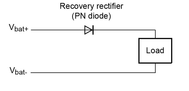
Figure 1. Using a recovery rectifier to provide RBP
The recovery rectifier acts as a blocking diode, which prevents current from flowing if the battery is connected with the incorrect polarity. This low complexity approach doesn’t require any input control, which reduces the number of components required. However, the high forward voltage drop of the PN junction in recovery rectifiers means they are usually only used for RBP in low power applications with load currents less than 1 Amp.With this approach, it is important to manage the inrush current when the battery is switched, causing the bulk capacitance of the rectifier to charge—the magnitude and duration of the peak pulse current does not exceed the specification. The steady state conduction loss (Ploss) is calculated from:
$$P_{loss} = I_{load} \times V_F(T)$$
where VF is the steady-state forward voltage drop of the diode given at the temperature of the PN junction, and Il is the load current. The forward voltage drop of the PN junction decreases by -1.9 mV/K as the device temperature rises, and while this results in lower power losses at higher temperatures, the maximum total power dissipation of the rectifier (specified in the device datasheet) cannot be exceeded.
Schottky Diode
Another simple way to implement RBP, which comes with the advantage of having lower conduction losses than using a recovery rectifier, is to use a Schottky blocking diode (Figure 2).
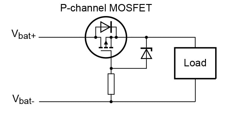
Figure 2. Using a Schottky diode to implement RBP
The lower forward voltage drop of the Schottky diode reduces device conduction losses, thus making it suitable for use in applications with higher load currents (up to 3 Amps). However, the metal-semiconductor interface in a Schottky diode means it has a higher leakage current than a PN diode.
Furthermore, device leakage current increases significantly as junction temperature increases, a feature that can result in potentially destructive thermal runaway. Similarly to the recovery rectifier, inrush current through the diode must be considered to ensure the junction temperature stays within the specified operating range.
P-channel MOSFET
Figure 3 shows a P-channel MOSFET being used to provide high-side RBP. This approach relies on the fact that P-channel MOSFETs have an internal body diode (source to drain). P-channel MOSFETs are ideal for use in high-side switching applications.

Figure 3. Using a P-channel MOSFET to implement RBP
When the battery is connected correctly, the positive terminal is connected to the drain of the MOSFET. Initially, as the battery voltage rises but the gate terminal voltage is not sufficiently negative (with respect to the source terminal), to enhance the device channel, the MOSFET is not ‘turned on’ in the conventional sense. Instead, its body diode allows current to flow, bypassing the MOSFET's channel and allowing power to be delivered to the load.
During this time, the power loss in the device is the product of the forward diode voltage and the current flowing through it. The forward diode voltage decreases with increase in temperature by -1.9 mV/K, meaning that as the load current (and hence die temperature) increases, power dissipation in the device reduces.
When the battery voltage rises to a level such that the gate-source threshold voltage is reached, the MOSFET then enters enhancement mode and transitions to ‘normal’ MOSFET operation. Current begins to flow in the drain-source channel and then the power loss is calculated as the product of the on-state resistance RDS(on) and square of the current flowing in the channel.
However, if the battery polarity is reversed (in other words, positive and negative terminals are swapped) for some reason, then the current flow is reversed. The MOSFET's body diode is now reverse-biased, thereby preventing current flow through the MOSFET's channel. To further protect the MOSFET against overvoltage conditions, a Zener diode and resistor can be added in series with the gate to source, as shown above. The Zener diode limits the voltage experienced across the gate to source terminals, thereby preventing damage to the device.
N-Channel MOSFET
The arrangement for using an N-channel MOSFET to provide low-side RBP is shown in Figure 4.
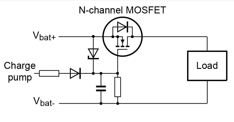
Figure 4. Using an N-channel MOSFET to implement RBP is more complex.
While N-channel MOSFETs have the advantage of being able to carry more current than their P-channel counterparts (due to having lower on-resistance), this approach is more complex and costly to implement because a charge pump is required in order to generate a positive gate-to-source voltage that exceeds the battery voltage which is crucial to enable the MOSFET to turn under correct polarity conditions.
Miniature P-channel MOSFETs Simplify Automotive RBP Integration
For many automotive applications where a cost-effective, small-footprint solution is the most important criteria, P-channel MOSFETs still offer sufficient current-carrying capacity. Recognizing this demand, Nexperia recently introduced its first P-channel MOSFET portfolio in ultra-compact and thermally efficient MLPAK33-WF packaging, which has a footprint compatible with the industry-standard DFN3333 and measuring only 3.3 x 3.3 mm.
This new series of devices complements Nexperia’s existing 5 mm x 6 mm P-channel offerings and broadening this portfolio further increases design flexibility by enabling even easier integration of reverse polarity protection circuitry into space-constrained automotive applications. These MOSFETs have low RDS(on) values, ranging from 8.2 mΩ to 66 mΩ at key voltages (30, 40 & 60 V) and have been tailored for efficient switching and minimal power loss. These devices have side-wettable flanks to facilitate automated optical inspection (AOI) and are AEC-Q101 qualified to provide automotive-grade reliability.
An Elegant High-Side Switching Solution
Reverse battery polarity protection is a fundamental requirement to protect in-vehicle safety subsystems from being damaged or destroyed if accidental miswiring occurs during servicing or repair. While diode-based approaches, such as recovery and Schottky rectifiers, offer simplicity, they incur significant conduction losses or leakage current concerns.
P-channel MOSFETs provide an elegant high-side switching solution with lower power dissipation and simplified gate control compared to N-channel alternatives, which require complex charge-pump circuitry. Nexperia’s newly launched automotive qualified portfolio of P-channel MOSFETs in a DFN3333-compatible packaging offers a robust and space-saving solution for automotive RBP, enabling designers to meet stringent power, size, and reliability targets in modern vehicle architectures.
All images used courtesy of Nexperia.