Facebook
 Google
 GitHub
 Linkedin
X-Series RFC Diodes for Robust and Reliable Medium-Voltage Drives
This article explains the popularity of the topology, the semiconductor requirements, and how the new X-Series diode module of MITSUBISHI ELECTRIC can make this converter more robust and more reliable
The three-level neutral-point-clamped converter is popular and often used in medium-voltage drives for instance. This article explains the popularity of the topology, the semiconductor requirements, and how the new X-Series diode module of MITSUBISHI ELECTRIC can make this converter more robust and more reliable.
Three-Level Neutral-Point-Clamped Converter
The three-level neutral-point-clamped converter (NPC) is a typical converter topology for high-power medium-voltage applications. The NPC converter is used in various applications: in offshore-wind generators, STATCOMs, rolling mills, conveyor starters, or even ship propulsion systems. What is special about this topology?

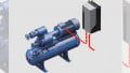
Figure 1: Three-Level Neutral-Point-Clamped (NPC) Converter made of IGBT modules (red) and diode modules (blue)
Figure 1 shows the principle schematic of an NPC converter. It consists of four main IGBTs which are marked in the figure by the red boxes. For one inverter arm, two IGBTs are connected in series. This gives the first advantage of the NPC converter: its dc-link voltage VDC can be twice as high compared to a two-level converter.
Furthermore, the NPC converter utilizes clamping diodes (marked by a blue box). Due to these diodes, the NPC converter is able to output three different voltage levels:
$$\left( + \frac{V_{DC}}{2} , 0 , - \frac{V_{DC}}{2} \right)$$.
The additional output level allows a lower total harmonic distortion (THD) compared to a two-level converter. This results in smaller and more efficient output filters.
As shown in Figure 1, the output voltage makes steps of:
$$ \frac{V_{DC}}{2}$$
This gives two advantages. Firstly, the switching losses of the semiconductors are lower, due to the lower switching voltage Vcc. Secondly, common-mode currents are reduced. These current might cause electro-magnetic interference (EMI) and damage of bearing and motors.
In summary, a three-level NPC converter offers the following advantages over a two-level converter:
- Higher achievable dc-link and output voltage
- Smaller, more efficient output filter
- Higher switching frequencies
- Lower common-mode currents
Application Field
The NPC converter is today used in various applications. Looking at three exemplary applications, we will see quite different technical converter requirements.
The first example is a grid-side converter of an offshore wind turbine injecting power from the wind generator into the grid. Therefore, the grid-side converter mainly operates at a power factor cos(φ) close to 1. It is operated directly at the grid or via a filter. Hence, only a small variation of the modulation index m are required.
As a second example, the generator-side converter of an offshore wind turbine is regarded. Since power flow is from AC- to DC-side, it is operated with a negative power factor. Moreover, the converter’s modulation index is varying according to the speed of the wind generator and the generator voltage.

Figure 2: RMS current in the clamping diode for different converter operation conditions
The last example is a STATCOM converter to supply reactive power to a grid. It might be operating at a power factor around 0 depending on the reactive power demand by the grid. Assuming a constant grid voltage, again the maximal modulation index is relatively constant.
The impact on the diode module of the three-level NPC converter (cf. Figure 1 blue box) for each application shall be analyzed. For this, an NPC converter with a constant dc-link voltage of 5000 V, a sinusoidal output current of 1500 A (RMS), switching frequency of 600 Hz and the output frequency of 50 Hz is considered.
Figure 2 shows the RMS current in the upper clamping diode as an indicator of the losses and the thermal stress of the diode module. It can be seen, that while the converter’s output current is 1500 A, the current through the clamping diode is lower. Secondly, it can be seen that the highest current occurs for low modulation indices. Finally, the figure reveals that the highest current occurs for a power factor around 0.
According to Figure 2, the current rating of the clamping diodes in a three-level NPC converter is highly dependent on the application. If chosen wrongly, the converter won’t be competitive in terms of performance or price. For every customer and every application, the optimal diode module has to be found, therefore.

Figure 3: Mitsubishi Electric high-voltage diode-module lineup
Due to this reason, Mitsubishi Electric offers a wide portfolio of IGBT as well as diode modules. An overview of the diode module line-up is given in Figure 3. High-Voltage diode modules are available from 1.7 kV to 6.5 kV blocking voltage. Moreover, diode generations range from S- and F-Series to X-Series, the newest development. The XSeries diode modules utilize the same RFC diodes like the X-Series IGBT modules. However, also the combination of X-Series IGBT together with an S- or F-Series diode module as a clamping diode can be considered. An exemplary measurement is shown in Figure 4.

Figure 4: Reverse recovery waveform of S-Series diode module switched with X-Series IGBT (RM600DG-130S, CM900HG-130X, Conditions: Tj = 25°C, Vcc = 3500 V, Ic = 1000 A, Ls = 150 nH)
X-Series RFC Diode
MITSUBISHI ELECTRIC now launches the new diode modules which use the same RFC diode chips, like in the X-Series IGBT modules.
Already in the IGBT modules, these diode chips have proven their
- High robustness and large safe operating area,
- Smooth switching even at high stray inductance,
- High surge current and I²t capability,
- High current ratings,
- Low power loss, and
- 150°C maximum junction temperature for all voltage classes.
These advantages are now transferred to dual-diode modules in the well-known 130x140 mm package. Figure 5 shows the 6.5kV diode module package as an example.

Figure 5: Outline a circuit diagram of a 6.5kV / 1000A diode module (type name: RM1000DG-130XA)
The RFC diode, which stands for Relaxed-Field at Cathode, has a special P and N+ doping pattern at the backside of the chip as illustrated in Figure 6. This backside pattern allows smooth switching transients (for low EMI) and strong robustness. This RFC diode has been proposed originally in [1]. Since then, it has been improved continuously [2] [3] [4] [5] [6].

Figure 6: Chip structure of the RFC diode
Figure 7 shows the forward voltage drop of two different 6.5 kV diode modules both in the same package outline. The Violet curve shows a 600 A module from a previous generation, the red curve shows the 1000 A X-Series diode module. Hence, the conduction losses have been reduced substantially. This allows for higher output power, higher efficiency, and more compact converters.

Figure 7: Comparison of 6.5 kV X-Series diode module (RM1000DG130XA) and previous generation in forward voltage drop for Tj =25°C
Also, the robustness of the diode was increased significantly. A typical measure for diode robustness is surged current or I²t capability. For it, the diode has to withstand a half-sine wave current pulse whose peak value is usually substantially higher than the nominal current rating. The peak value of the surge current or the integral of the current-squared is usually indicated in the datasheet. A larger surge current capability is desired for example in case of a short circuit at in the converter.
![3.3 kV X-Series diode switches off at high dc-link inductance (Ic = 1800A, Vcc = 1800V, Tj = 25°C, Ls = 300 nH) [1 µs/div, 500 V/div (red), 1000 A/ div (blue)]](https://eepower.com/uploads/articles/X-Series_Rfc_Diodes_For_Robust_And_Reliable_Medium-Voltage_Drives_Figure_8.jpg)
Figure 8: 3.3 kV X-Series diode switches off at high dc-link inductance (Ic = 1800A, Vcc = 1800V, Tj = 25°C, Ls = 300 nH) [1 µs/div, 500 V/div (red), 1000 A/ div (blue)]
Comparing the surge current capability of the new 4.5 kV X-Series RFC diode with an older generation shows the big improvement. Consequently, surge current capability and I²t capability are increased by 38 % and 129 % respectively.
Especially in multi-level converters, the parasitic inductance Ls of the dc-link might increase substantially due to more complex busbars and larger commutation loops. Figure 8 shows the switching waveform of a 3.3 kV X-Series diode at large dc-link inductance of 300 nH. Even at these extreme conditions, the X-Series diode shows an expected and smooth switching behavior. This allows robust converter operation and a fast design-in process.
Conclusion
Complementary to the well-accepted S- and F-Series diode modules, MITSUBISHI ELECTRIC just launched the new X-Series diode modules. From a large line-up, the optimal diode for applications like multilevel converter or dc choppers can be chosen. The X-Series diode modules use the latest development of the RFC diode. This increases the maximum current capability but also enhances the robustness of the diode. This is manifested by the increased surge current and I²t capability. This, and the well-tempered switching behavior, allow reliable and robust medium-voltage converters.
About the Authors
Nils Soltau received the Diploma degree in electrical engineering and information technology from RWTH Aachen University, Aachen, Germany, in 2010.,Since March 2010, he has been with the Institute for Power Generation and Storage Systems (PGS), E.ON Energy Research Center, RWTH Aachen University, where he builds up a 5 MW dc–dc converter. His research interests include high-power dc–dc converters, medium-voltage power semiconductors, and magnetic components.
Hitoshi Uemura received the B.E. and M.E. degrees in applied Electrical Engineering from University of Nagasaki in 2003 and 2005. In 2005, he joined the Power Device Works of Mitsubishi Electric Corporation, where he works on the High Voltage design & development Dept.
Kenji Hatori works as an Assistant Manager on Project Management at the Mitsubishi Electric Corporation, Fukuoka Japan, a branch of the Japanese multinational electronics and electrical equipment company, Mitsubishi Electric Corporation, that specializes in power device works.
References
- K. Nakamura, H. Iwanaga, H. Okabe, S. Saito und K. Hatade, „Evaluation of oscillatory phenomena in reverse operation for High Voltage Diodes,“ in 21st International Symposium on Power Semiconductor Devices & IC's, Barcelona, 2009.
- K. Nakamura, F. Masuoka, A. Nishii, K. Sadamatsu, S. Kitajima und K. Hatade, „Advanced RFC technology with new cathode structure of field limiting rings for High Voltage planar diode,“ in 22nd International Symposium on Power Semiconductor Devices & IC's (ISPSD), Hiroshima, 2010.
- A. Nishii, K. Nakamura, F. Masuoka und T. Terashima, „Relaxation of current filament due to RFC technology and ballast resistor for robust FWD operation,“ in 23rd International Symposium on Power Semiconductor Devices and ICs, San Diego, 2011.
- F. Masuoka, K. Nakamura, A. Nishii und T. Terashima, „Great impact of RFC technology on fast recovery diode towards 600 V for low loss and high dynamic ruggedness,“ in 24th International Symposium on Power Semiconductor Devices and ICs, Bruges, 2012.
- F. Masuoka, K. Tanaka, T. Kachi, Y. Yoshiura und K. Shimizu, „RFC diode with high avalanche stability and UIS capability,“ in 29th International Symposium on Power Semiconductor Devices and IC's (ISPSD), Sapporo, 2017.
- K. Nakamura und K. Shimizu, „Advanced RFC diode utilizing a novel vertical structure for soilness and high dynamic ruggedness,“ in 29th International Symposium on Power Semiconductor Devices and IC's (ISPSD), Sapporo, 2017.
This article originally appeared in the Bodo’s Power Systems magazine.