Facebook
 Google
 GitHub
 Linkedin
What is a Voltage Source?
This article highlights the meaning of independent and dependent voltage sources.
This series will provide a look at each of these electrical sources of energy: light, pressure, friction, chemicals, heat, and magnetism.
Batteries can be represented by an ideal voltage source in series with the internal resistance of the battery. Because an ideal voltage source is assumed to have a voltage that does not change, it is termed a constant-voltage source.
An ideal voltage source maintains a constant output voltage regardless of its load resistance. For example, let's say that the voltage source in Figure 1a is an ideal voltage source. As shown in the figure, the voltage across the open terminals of the source is 10V. This "open-terminal" voltage is referred to as the no-load output voltage (VNL). When the various load resistances shown in Figure 1b are connected to the source, it maintains the same 10 V output. Thus, for an ideal voltage source, regardless of the value of the load resistance, we have:
VNL=VRL
where VRL denotes the voltage across the load resistance.
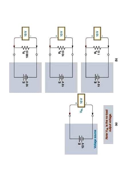
Figure 1. The output voltage of an ideal voltage source does not change under (a) no-load and (b) loaded conditions.
For any practical voltage source, a decrease in load resistance results in a decrease in the source output voltage. This lies in the fact that every voltage source has some amount of internal source resistance, as represented by the resistor (RS) in Figure 2a. When a load is connected to the source, as shown in Figure 2b, it forms a voltage divider with the internal resistance of the source. This causes VRL to be lower than the no-load output voltage (VNL), as demonstrated in Example 1.
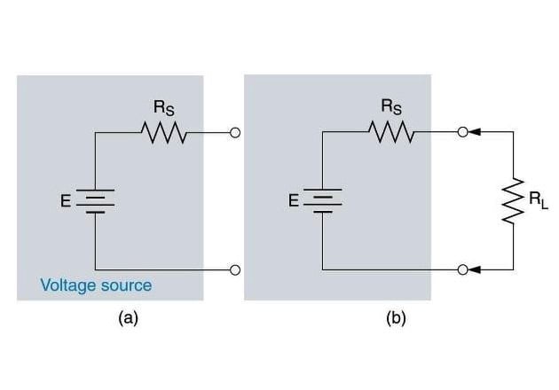
Figure 2. A practical voltage source
Example 1: Calculating VRL
The no-load output voltage of the source in Figure 3 is 12V. Calculate the values of VRL for RL= 100Ω and RL=20Ω
Figure 3. Voltage source (E) with the load resistance (RL)
Solution
The load resistance forms a voltage divider with the internal resistance of the source (RS). When RL=100 Ω, VRL is found as:
When RL =20 Ω, VRL is found as:
As you can see, the decrease in load resistance caused a drastic decrease in VRL.
The internal resistance of most DC voltage sources is 50Ω or less. As such, it does not present a major problem for loads in the kΩ range or higher. However, it can cause a significant drop in output voltage when a low-resistance load is present. This is why low internal resistance is considered desirable for a DC voltage source.
Parallel and Series Operation
Voltage sources can be operated in series without difficulty. Figure 4a shows two series-connected voltage sources, and Figure 4b shows the equivalent circuit. The no-load voltage of the equivalent circuit is the sum of the no-load voltages of the individual sources , and the resistance of the equivalent circuit is the sum of the resistances of the individual sources.
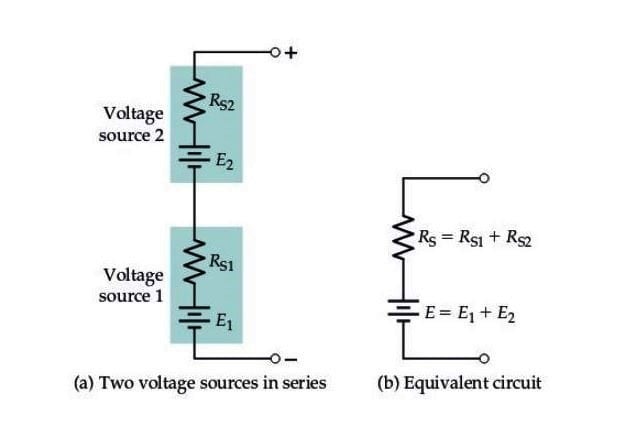
Figure 4. (a) Voltage sources can be operated in series without difficulty, (b) the equivalent output voltage is the sum of the no-load voltages of the no-load voltages of the individual sources, and the equivalent source resistance is the sum of the individual source resistances.
Voltage sources can be operated in parallel only if the source voltages are equal. As illustrated in Figure 5a and 5b, the resistance of the resistance of the equivalent circuit is the parallel combination of the individual source resistances, and the no-load voltage of the equivalent circuit, of course, is equal to that of the original parallel-connected voltage sources. Figure 5c shows that when sources with unequal voltages are connected in parallel, the lower-voltage source will tend to discharge the higher-voltage source.
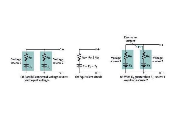
Figure 5. (a) Voltage sources with equal voltages can be operated in parallel, (b) the equivalent circuit of parallel-connected voltage sources, (c) voltage sources with unequal voltages should not be connected in parallel.
Independent Voltage Source
A source that does not depend on any other quantity (like voltage or current) in the circuit is termed an independent source. The following figure shows some common symbols for representing independent voltage sources:
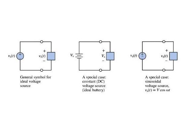
Figure 6. (a) DC voltage source; (b) battery symbol; (c) AC voltage source symbol
If you connect an ideal independent voltage source to a resistive circuit or a circuit that contains an arbitrary combination of resistors, inductors, and capacitors, the output voltage of the source won’t change. Even if you double up the value of these components, the value of the independent voltage source will still remain constant.
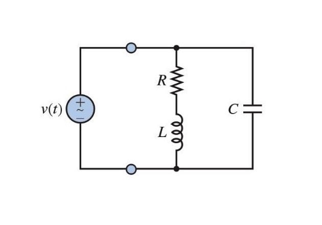
Figure 7. An independent ideal voltage source exhibits a constant output voltage when connected to an arbitrary combination of different circuit elements
Dependent Voltage Sources
As the name suggests, the dependent (or controlled) voltage sources are ones whose output voltage depends on some other voltage or current in the circuit. The following symbol is used to represent the dependent voltage source:
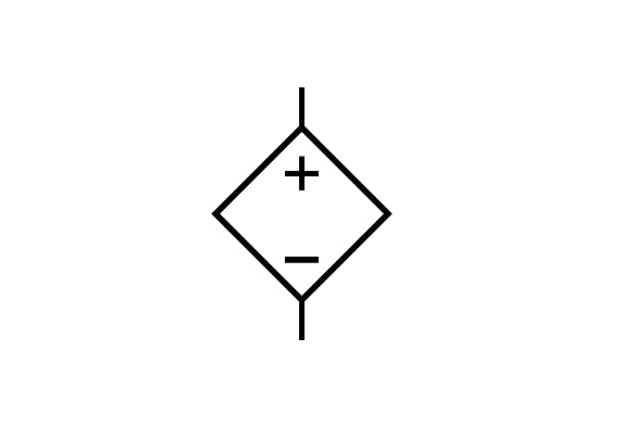
Figure 8. Dependent voltage source symbol
Now, let's work to understand dependent voltage sources through an example.
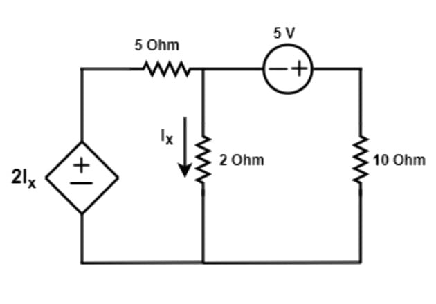
Figure 9. Dependent voltage source example
In the circuit above, we have one dependent voltage source. The value of this source is given by the expression 2Ix; where Ix is the current flowing through the 2-ohm resistor. So, as the current flowing through this 2-ohm resistor changes, the voltage source's value also changes. Thus, we can conclude that the current Ix is controlling the voltage of this voltage source.
There are two types of dependent voltage sources. The first one is a current-controlled voltage source (CCVS), and the second one is a voltage-controlled voltage source (VCVS).
Current Controlled Voltage Source (CCVS)
The following diagram represents the current-controlled voltage source:
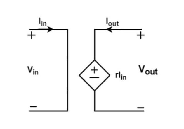
Figure 10. Current controlled voltage source representation
Here, you can see that the current Iin is controlling the output voltage of the dependent voltage source. The output voltage can be written as:
Where Iin is the current that controls the value of the dependent voltage source and r is a coefficient having the unit of resistance. Sometimes, this r is also known as trans-resistance.
Example 2: CCVS
An op-amp configured in a trans-conductance mode (Figure 11 below) acts as a CCVS. The output voltage of the op-amp depends on the input current. As the input current Ii changes, the output voltage changes by the following expression:
Vo = Li RL
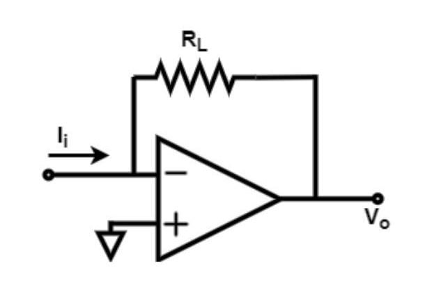
Figure 11. An op-amp in trans-conductance mode; an example of a CCVS.
Voltage-Controlled Voltage Source (VCVS)
The following diagram represents the voltage-controlled voltage source:
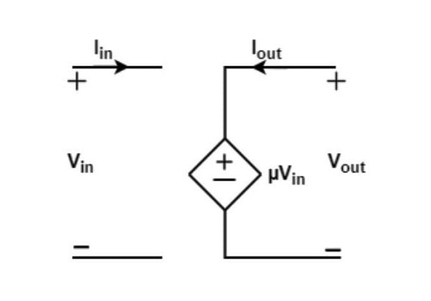
Figure 12. Voltage-controlled voltage source representation.
Here, a voltage quantity, Vin, controls the value of the dependent voltage source. The output voltage Vout can be written as:
Where Vin is the input voltage that is controlling the voltage of this voltage source and µ is a unit-less coefficient. The coefficient µ is also known as voltage transfer ratio.
Example 3: VCVS
When we configure an op-amp in an inverting or non-inverting configuration, It acts as a VCVS. Once we adjust the gain, the output voltage Vo depends on the input voltage Vi. As we change Vi, the output voltage changes accordingly by the following expression:
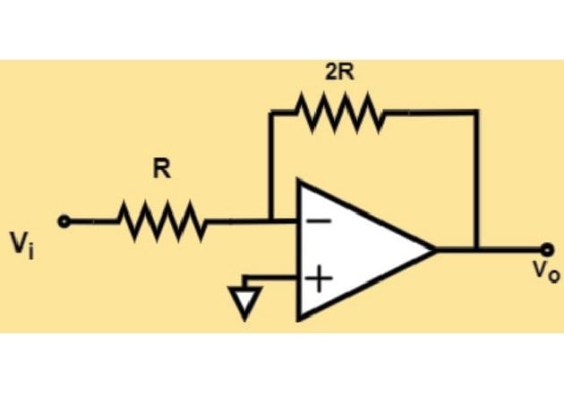
Figure 13. An op-amp in inverting configuration; an example of a VCVS.
The Bottom Line
An ideal voltage source provides a constant output, regardless of the value of its load resistance RL. A practical voltage source, on the other hand, has an output voltage that varies with RL. This means that a change in the load resistance will cause a change in the load voltage. The characteristics of ideal and practical voltage sources are summarized in Figure 14.
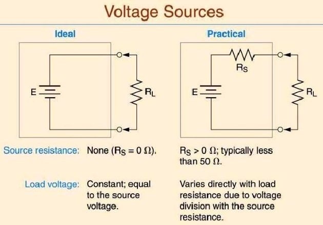
Figure 14. Ideal vs. practical voltage sources