Facebook
 Google
 GitHub
 Linkedin
Using Low-Voltage Devices in High-Voltage Server Power Supplies—Part 1
The increasing power demand in data centers, led by advances in artificial intelligence, is driving the need for converters with higher power density and efficiency. Part one of this three-part series features an overview of low-voltage devices in high-voltage server power supplies.
This article is published by EEPower as part of an exclusive digital content partnership with Bodo’s Power Systems.
The increasing power demand in data centers, led by advances in artificial intelligence, is driving the need for converters with higher power density and efficiency. These converters typically consist of two stages: a Power Factor Correction (PFC) circuit and an Isolated DC-DC converter.
The PFC operates from a supply voltage of 240 VAC and generates a 400 VDC bus. The DC-DC stage down converts to 50 V while providing isolation. In addition, such power supplies must comply with the recent requirements released by the Open Compute ORV3 standard and fit within the specific form factor and dimensions.

Figure 1. Two-stage server power supply, grid AC to 50 V intermediate bus. Image used courtesy Bodo’s Power Systems [PDF]
Part one of this three-part series features an overview of low-voltage devices in high-voltage server power supplies.
Low-Voltage Devices in High-Voltage Topologies
Traditional power supplies use two-level topologies built around the half-bridge and employ Wide-Bandgap (WBG) high-voltage devices. To achieve higher power, the high-voltage devices need low on-state resistance and, in some cases, require multiple devices connected in parallel. None of these classic techniques significantly increase power density. Alternatively, low-voltage devices can be used in conjunction with multi-level topologies and cascade configurations to increase power density beyond that of high-voltage devices.
Multi-Level Topology
A multi-level topology breaks the high voltage into multiple lower voltage levels using a series connection of devices and capacitors that set the respective levels. A popular topology is the flying capacitor approach, shown in Figure 2, configured as a totem-pole power factor correction circuit with four levels.

Figure 2. Totem-pole, multi-level PFC converter. Image used courtesy Bodo’s Power Systems [PDF]
Cascade Configuration
In a cascade configuration, multiple converters are connected in series to build up the required voltage on the input, with the outputs connected in parallel, as shown in Figure 3. This works if the converters used in the cascade are voltage-sourced and isolated.

Figure 3. Cascade configuration for a fixed ratio isolated converter. Image used courtesy Bodo’s Power Systems [PDF]
Performance Comparison: High vs. Low Voltage Devices
A 5 kW, 240 VAC to 50 VDC power supply system comprising a PFC stage and an isolation stage with a 400 VDC interim bus will serve as a baseline to compare high voltage with low voltage device approaches. The PFC stage is hard-switching using a totem-pole configuration, while the isolation stage is soft-switching based on an LLC. Both topologies are popular choices for server power supplies.
The first comparison is a multi-level adaptation of a comprehensive hard-switching Figure-of-merit (FOM) applicable to the PFC converter. The components are given in equations (1) through (3) and combined in equation (4), where a lower value yields better performance.
\[FOM_{1}=R_{DS(on)}\cdot Q_{G}\cdot(N-1)^{2}\,\,\,\,\,(1)\]
\[FOM_{2}=R_{DS(on)}\cdot Q_{OSS}\,\,\,\,\,(2)\]
\[FOM_{3}=R_{DS(on)}\cdot Q_{RR}\cdot(N-1)^{2}\,\,\,\,\,(3)\]
\[FOM_{ML}=\sqrt{FOM_{1}^{\,\,2}+FOM_{2}^{\,\,2}+FOM_{3}^{\,\,2}}\,\,\,\,\,(4)\]
A 5 kW PFC requires approximately 15 mΩ for each high voltage switch, and the equivalent is three devices connected in series in the 4-level flying capacitor configuration. For the comparison a 650 V rated SiC MOSFET, a 650 V rated Cascode GaN FET, two paralleled 650 V rated enhancement mode GaN FETs, all of which are suitable for use in both the PFC and LLC, are compared to the 200 V rated GaN FET for the 4-level PFC and the 150 V rated GaN FET for the 4-cascade LLC, with the results given in table 1. Since the cascade configuration uses four stacked converters, it is equivalent to a 5-level converter.
From Table 1, the lower voltage devices have significantly lower FOM than any of the high voltage devices, regardless of technology.
Table 1. Multi-level Figure of merit comparison between 650 V, 200 V, and 150 V devices used in 2-level, 4-level PFC, and 4-cascade configuration converters, respectively.
|
Device |
Technology |
VDS (V) |
VG (V) |
RDSon typ (mn) |
QG (nC) |
QOSS (nC) |
QRR (nC) |
Levels (N) |
FOMML (mΩ.nC) |
|
IMW65R015M2H |
SiC MOSFET |
650 |
18 |
14.5 |
79 |
148 |
221 |
2 |
4024 |
|
TP65H015G5WS |
Cascode GaN FET |
650 |
10 |
15 |
74 |
430 |
430 |
2 |
9189 |
|
2x GS66516T-MR |
Enhanced GaN FET |
650 |
5 |
12.5 |
28.4 |
268 |
0 |
2 |
3369 |
|
EPC2304 |
Enhanced GaN FET |
200 |
5 |
3.1 |
24 |
116 |
0 |
4 |
761 |
|
EPC2305 |
Enhanced GaN FET |
150 |
5 |
2.2 |
22 |
103 |
0 |
5 |
807 |
The next converter characteristic for comparison is differential mode EMI. In either a multi-level converter or cascade configuration, any switching event voltage will always be much lower than that of a 2-level converter topology. That lower voltage transition reduces differential mode EMI energy proportionally. In addition, lower voltage devices tend to switch faster, thus increasing their EMI frequency content. A simulation of a PFC converter was performed that included a single common-mode choke stage EMI filter and equivalent circuit for an LISN with differential mode conducted EMI output. The comparison result between a 2-level and 4-level totem-pole PFC is shown in Figure 4. The 4-level converter is approximately 40 dB lower than the 2-level converter.

Figure 4. Simulated and conducted differential-mode EMI comparison between a 2-level half-bridge and 4-level flying capacitor totem-pole PFC converter using a single common-mode choke EMI filter. Image used courtesy Bodo’s Power Systems [PDF]
The final benefit of using low-voltage devices in high-voltage applications is the reduction in magnetic component size. For the flying capacitor multi-level converter, the number of levels reduces the inductance of the main inductor by a factor of (N – 1)2, where N is the number of levels when the ripple current magnitude is kept the same. Thus, for a 3-level configuration, a factor of 4 reduction can be expected, and for 4-levels, a reduction factor of 9 can be expected.
In addition to size reduction, the lower inductance increases the closed current loop control response, thus making it easier to comply with stricter THD standards for the grid.
For the cascade approach, the transformer requires fewer winding turns, which opens the possibility of using standard PCB technology and planar magnetics for construction. These magnetic component reductions increase power density and reduce cost. In addition, the lower voltage transformer can operate at much higher frequencies, further reducing magnetic component size.
Modularity
The inherent characteristic of the cascade configuration is modularity, where low-voltage input modules are stacked to achieve a higher input voltage for a system. The design of these modules is much simpler than that of higher voltage counter parts, in large part due to the lower turn count of the transformer winding. It is also easy to scale to accommodate higher voltages, such as 400 V and 800 V sources, by simply adding additional modules to the stack.

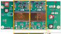
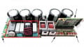
Figure 5. (A) 5 kW 4-level PFC converter module, (b) 1.25 kW 100V to 50 V LLC converter module building block for a 5 kW cascade converter. Image used courtesy Bodo’s Power Systems [PDF]
In the case of multi-level converters, their smaller inductor size also allows the design to be modular. Such modularity makes it easy to add additional phases to increase power.
The modularity of low voltage device solutions is shown in Figure 5(a) for a 240 VAC to 400 VDC, 5 kW multi-level converter module and Figure 5(b) for a 1.25 kW, 100 VDC to 50 VDC LLC converter module suitable for use in a 400 VDC to 50 VDC cascade system.
Stay Tuned for Parts 2 and 3
Part 1 of this article presented an overview of using low voltage GaN devices in high voltage applications, with examples of a 240 VAC source 5 kW totem pole PFC and 400 VDC to 50 VDC isolated LLC converter. A FOM analysis revealed significant improvement in performance can be achieved using lower voltage devices. The benefits extend to increased power density through reduced magnetic component size and lower EMI filter requirements. Part 2 will cover the details of the multi-level PFC converter. Part 3 will cover the details of the Isolation converter.
This article originally appeared in Bodo’s Power Systems [PDF] magazine and is co-authored by Michael de Rooij, Vice President of Applications, Alejandro Pozo, Senior Applications Engineer, and Marco Palma, Director, Motor Drives Systems and Applications, all Efficient Power Conversion.