Facebook
 Google
 GitHub
 Linkedin
Using Low-Voltage Devices in High-Voltage Server Power Supplies—Part 3
In this third and last part of the series we delve into the Isolated DC-DC converter that follows the PFC.
This article is published by EEPower as part of an exclusive digital content partnership with Bodo’s Power Systems.
Article co-authored by Efficient Power Conversion's Alejandro Pozo and Marco Palma.
In part one of this series, we presented some of the benefits of multilevel topologies for the AC/DC and Isolation DC/DC stages in a server power supply. A brief introduction to popular examples of both was presented.
Part two of the series focused on the AC/DC stage and showed the key features of a four-level totem-pole PFC converter. Details of the hardware and control algorithm were shown, as well as its performance when operating from a 240 VAC input and delivering up to 5 kW into a 400 VDC bus.
Figure 1 shows the block diagram of a fixed-ratio converter, with four LLC modules arranged in an input-series, output-parallel (ISOP) configuration. The converter can process up to 5.5 kW between the 400 VDC input bus and a 50 VDC output bus, while offering galvanic isolation between them.
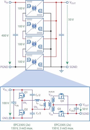
Figure 1. Block diagram of the ISOP LLC converter and simplified schematic of the LLC modules. Image used courtesy of Bodo’s Power Systems [PDF]
Converter Overview and Benefits
The converter shown in Figure 1 utilizes four isolated LLC converters in an ISOP configuration. It has an overall input-to-output voltage ratio of 8:1, so each LLC converter only experiences a quarter of the input voltage and processes a quarter of the total output power. As a result, low-voltage devices with better figures of merit than high-voltage components [1, 2] can be used.
Moreover, the design of each LLC converter is greatly simplified due to the lower power rating needed as well as the lower conversion ratio required of 2:1. In this example, when the input voltage is 400 VDC with a total output power of 5.5 kW, each LLC module only has 100 V at its input and delivers 1375 W into the common 50 V output.
The topology selected for each LLC module is based on a primary half-bridge with split capacitors and a center-tap full-wave rectifier. The same 150 V-rated and 2.2 mΩ-typical GaN transistors, EPC2305 [3], are used in the primary and rectifier sockets of the LLC.
This is possible because in this implementation, all FETs experience the same voltage stress and similar RMS current. Consequently, a minimum FET count is realized for each module, unlike Ma et al [4], and the design of the transformer is greatly simplified, enabling a planar solution with the windings built into a printed circuit board (PCB) with as few as 8 layers.
A key property of ISOP LLC converters is their ability to self-balance the input voltages for each module without a dedicated circuit or control algorithm [4]. This is achieved by design using a high magnetizing inductance (Lm) to resonant inductance (Lr) ratio, yielding a wide frequency range around the operating point in which the gain is largely independent of component tolerances.
In addition, the configuration discussed in this article renders additional benefits compared to a single module solution. First, there is the possibility to phase shift the operation of each LLC module to reduce the output current ripple and minimize the total output capacitance. Second, the lower voltage stress on all the components within each LLC module allows a smaller size and lower component height. And third, the distributed nature of the power losses over a larger area simplifies the thermal solution.
Hardware
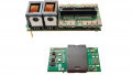
Figure 2 shows the hardware implementation of the experimental 400 V to 50 V, 5.5 kW ISOP LLC converter. It was designed to meet the physical dimensions specified by the Open Compute Project (OCP) ORv3 48 V PSU Specification [5]. The unit consists of a motherboard and four identical LLC-module boards, two plugged into the top side and two on the bottom side of the motherboard.
The motherboard also hosts the controller, a dsPIC33CK from Microchip, input and output bus ceramic capacitors, and signal and power connections to each LLC module. The LLC modules are implemented on four identical boards, each with all the necessary components to be operated as a standalone 100 V to 50 V, 1375 W isolated converter.
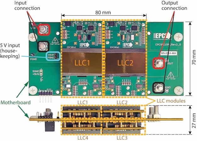
Figure 2. Top and front photos of the EPC91110KIT ISOP LLC converter [6]. Image used courtesy of Bodo’s Power Systems [PDF]
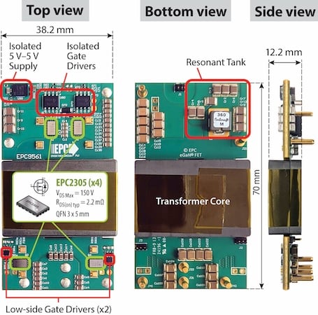
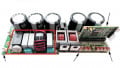
Figure 3. Photos of the LLC-module board with various components highlighted. Image used courtesy of Bodo’s Power Systems [PDF]
Figure 3 shows photos of one LLC module with the main components highlighted.
The GaN transistors in the primary side of the LLC are controlled with two isolated gate drivers. In all the modules, the input side of the gate drivers is referenced to the secondary-side ground (SGND in Figure 1), common with the controller. The output side of the gate drivers is different for each module (GNDi in Figure 1), depending on their relative position within the ISOP configuration. A small isolated 5 V – 5 V power supply [7], combined with a conventional bootstrap circuit, is used to power the output side of the isolated gate drivers within each module.
The transformer core is based on a standard E + I geometry using Proterial’s ML95S material, although other materials were also tested with some differences in performance. The windings of the transformer are built into 6 of the 8 layers of the PCB, with a copper thickness of 2 oz.
The air gap of the core was adjusted to realize ZVS turn-on in the primary FETs. The resonant tank, mostly located on the bottom side of the PCB, comprises several C0G ceramic capacitors and an external 36-nH ferrite-based inductor to establish a resonant frequency of approximately 1 MHz. The switching frequency of the GaN FETs is set to match the resonant frequency to minimize losses.
Experimental Results
The experimental unit shown in Figure 2 was operated between a 410 VDC input and a 51 VDC output while delivering up to 5.5 kW. Two transformer variants were evaluated using the same converter schematic and components, transformer core geometry, PCB stack-up, and turns ratio.
The only difference between variants is the number of turns for each winding. Efficiency and power losses for both designs are provided in Figure 4. One variant uses a 2:2:2 turn transformer, having one PCB layer for each turn, while the other variant uses a 1:1:1 turn design, where each winding comprises two turns in parallel.
The former achieves a peak efficiency of 98.5% and full-load efficiency of 97.5%, while the latter reaches 98.2% peak efficiency and approximately 98% at full load. These numbers are the result of a trade-off between core losses, which dominate the low-load losses for the 1:1:1 design, and winding losses, which are the main loss mechanism in the 2:2:2 variant.
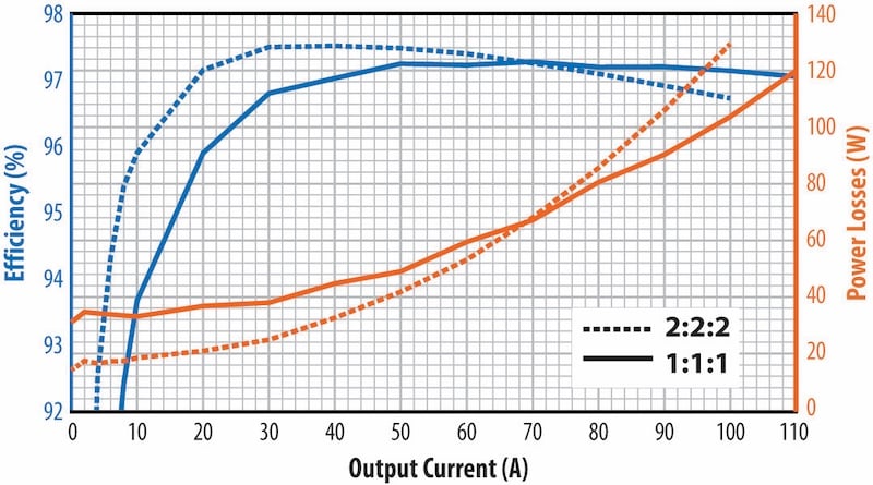
Figure 4. Efficiency and Power Losses with Vin = 410 VDC, Vout = 51 VDC, operation for two transformer variants. Image used courtesy of Bodo’s Power Systems [PDF]
Concurrently, the input voltages for each LLC module within the converter were recorded for both transformer variants at various output powers. The results are presented in Figure 5, demonstrating excellent voltage sharing among the modules to within 2% of the 100 V.
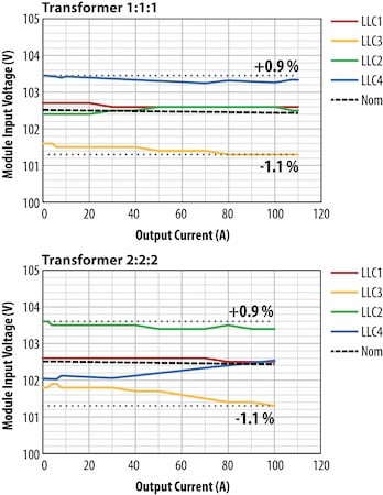
Figure 5. Differential input voltages of all LLC modules for both transformer variants operating from a 410 V input bus and delivering up to 5.5 kW into a 51 V bus. Image used courtesy of Bodo’s Power Systems [PDF]
Scalability to High Voltage and Higher Power
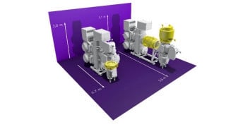
The growth in Artificial Intelligence (AI) caused the data center electricity usage to more than double between 2017 and 2023, and the trend is expected to accelerate even more in the next few years [8]. This increasing demand for power is driving changes in the architecture of the power distribution in server racks, shifting from a 50 VDC distribution bus to an 800 VDC or ±400 VDC bus [9].
Fortunately, the ISOP converter presented in this article can be easily repurposed as an 11 kW, 800 V to 50 V or a ±400 to 50 V, without significant changes to the LLC module and overall converter, by simply adding additional modules to the ISOP configuration.
With the goal to increase the processing power per rack (i.e., more GPUs per rack), changes in the server rack are expected to extend beyond the power supply, as we have seen recently in prototypes from some of the key players in the industry [10]. In this new architecture, the isolation stage is integrated into the IT motherboard.
Liquid cooling and a more demanding height restriction increase the need for higher power density, while requiring even larger conversion ratios such as 16:1 (800 VDC – 50 VDC) or 64:1 (800 VDC – 12.5 VDC). Therefore, the benefits of a modular approach like the ISOP LLC converter discussed in the previous sections could become the enabling technology.
Conclusions
This article presented a fixed-ratio, 5.5 kW, 400 VDC to 50 VDC isolated converter using only 150 V-rated GaN transistors in a simple ISOP configuration. The experimental results demonstrate peak efficiencies well above 98% and full load efficiency of 98% while achieving a power density of 596 W/in3 (36.4 W/cm3). Self-balancing of the cascaded LLC inputs is realized by design, avoiding dedicated components or control schemes. Moreover, the combination of ISOP LLCs with low-voltage GaN devices offers an ideal solution for the increasing demand for power in servers.
References
[1] A. Lidow, M. De Rooij, J. Glaser, A. Pozo, S. Zhang, M. Palma, D. Reusch, and J. Strydom, “GaN Transistors for Efficient Power Conversion,” 4th ed. John Wiley & Sons, 2025. ISBN: 978- 1394286959
[2] A. Pozo and M. A. de Rooij, “5.5 kW Isolated 400 V to 50 V DCDC Converter for Server Power Supplies,” PCIM Conference 2025; International Exhibition and Conference for Power Electronics, Intelligent Motion, Renewable Energy and Energy Management, Nürnberg, Germany, 2025, pp. 637-645
[3] Efficient Power Conversion, “EPC2305 - Enhancement Mode Transistor,” [online]. Available: https://epc-co.com/epc/portals/0/epc/documents/datasheets/EPC2305_datasheet.pdf
[4] Q. Ma, Q. Huang and A. Q. Huang, “Zero-Voltage Switching and Natural Voltage Balancing of a 3 kW 1 MHz Input-Series-Output-Parallel GaN LLC Converter,” in IEEE Open Journal of Power Electronics, vol. 5, pp. 1119-1128, 2024
[5] Open Compute Project, Open Rack/SpecsAndDesigns, “Open Rack V3 48V 5.5kW PSU Specification,” Rev. 0.4, October 12, 2024. [Online] www.opencompute.org/wiki/Open_Rack/SpecsAndDesigns
[6] Efficient Power Conversion, “EPC91110KIT: 5.5 kW, 8:1 fixed ratio, 400 V to 48 V Isolated Converter with EPC2305 GaN FETs,” [online]. Available: https://epc-co.com/epc/products/evaluation-boards/epc91110
[7] Monolithic Power Systems, “MIE1W0505BGLVH 5V, 1W, Regulated, 2.5kVRMS Isolated DC/DC Module,” [online]. Available: https://www.monolithicpower.com/en/mie1w0505bglvh.html
[8] Shehabi, A., Smith, S.J., Hubbard, A., Newkirk, A., Lei, N., Siddik, M.A.B., Holecek, B., Koomey, J., Masanet, E., Sartor, D. 2024. 2024 United States Data Center Energy Usage Report. Lawrence Berkeley National Laboratory, Berkeley, California. LBNL-2001637
[9] M. Blake, M. Hsu, I. Goldwasser, H. Petty and J. Huntington. May 20th 2025. “NVIDIA 800 VDC Architecture Will Power the Next Generation of AI Factories,” Nvidia Developer, Technical Blog Data Center/Cloud [online]. Available: https://developer. nvidia.com/blog/nvidia-800-v-hvdc-architecture-will-powerthe-next-generation-of-ai-factories/
[10] J. Walton. March 19th 2025. “Nvidia shows off Rubin Ultra with 600,000-Watt Kyber racks and infrastructure, coming in 2027,” tom’s hardware.com [online]. Available: https://www. tomshardware.com/pc-components/gpus/nvidia-shows-offrubin-ultra-with-600-000-watt-kyber-racks-and-infrastructurecoming-in-2027
This article originally appeared in Bodo’s Power Systems [PDF] magazine and is co-authored by Alejandro Pozo, Michael de Rooij, and Marco Palma, all Efficient Power Conversion