Facebook
 Google
 GitHub
 Linkedin
Understanding the Design Basics of Isolation Transformers
Learn about the different types of isolation transformers and how they are designed.
Isolation transformers act as a buffer between the load and the power source. Isolation transformers are used to provide cleaner power to nonlinear loads and to prevent harmonics from moving upstream into the power source. Isolation transformers, as well as reactors, can be used to reduce distortion of the motor drive current.
Isolation transformers provide reactive control of current harmonics for both AC and DC motor drives, whether they are the static bridge or the silicon-controlled rectifier (SCR) switch input type. Reduction of current harmonics improves line current waveform distortion, thereby improving the power factor of the drive load and reducing voltage waveform distortion effects in the feeders ahead of the transformer.
Drive Isolation Transformers
Drive isolation transformers are specially designed isolation transformers that are placed between the system supply power and an electronic motor drive or group of drives (see Figure 1). The three basic functions performed by drive isolation transformers are voltage change, reduction of drive-induced ground currents, and reduction of common-mode noise. They provide similar benefits for both DC drives and variable-frequency AC drive applications.
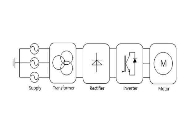
Figure 1. Drive isolation transformers are placed between a power source and a motor drive. Image Courtesy of MDPI Journal
All two-winding transformers are isolation transformers. However, general-purpose transformers aren't fully rated for motor drive applications since they can't withstand high distortion levels at full load without overheating. Furthermore, mechanical stress shortens the life expectancy of many standard transformers when they supply DC motor drive current transients. The severe cyclic nature of motor drive process control applications is another contributor to shortened life expectancy.
Design
Special designs are needed for transformers used as drive isolation transformers. A drive isolation transformer is designed with additional reactance to reduce power quality problems associated with the effects of nonlinear loads (see Figure 2). A drive isolation transformer must be able to withstand the heating effects of the nonlinear drive loads and operate well above the ambient temperature.
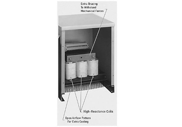
Figure 2. Drive isolation transformers have extra bracing to withstand mechanical forces, high-reactance coils to control current flow, and increased airflow for extra cooling.
Drive isolation transformers must also withstand the thermal and mechanical stresses caused by the highly cyclic load demands of both AC and DC motor drive applications. Many loads have characteristics that are similar to AC and DC motor drives. This is due to the fact that the load inputs are designed either with 3-phase static diodes or 3-phase, six-pulse SCR bridge rectifier circuits. Drive isolation transformers can also control the impact of such loads on the primary power system. Drive isolation transformers are used in a variety of applications, including 3-phase rectifier input DC power supplies, SCR-controlled furnace heating, and 3-phase switched-mode power supplies.
The benefits provided by drive isolation transformers can vary and are system-related. For example, some issues with harmonic distortion are the result of drives that are too large for the user's supply capacity. Another issue could be the result of the drive and affected loads sharing long service lines with a large source impedance. Under these conditions, the additional reactance of drive isolation transformers may provide little or no improvement in related problems. Solutions for such installations typically are to reroute distribution lines and loads or to install harmonic filters at appropriate locations in the electrical system.
Grounding and Shields
Proper grounding practices along with drive isolation transformers are used to reduce the effects of common-mode noise. If the secondary of a drive isolation transformer is wye-connected, it can be grounded (see Figure 3). In general, grounding the secondary has three significant benefits. Grounding provides superior transient and impulse immunity to the load side of the transformer. Grounding reduces common-mode noise coupling from primary to secondary. Induced ground current does not transfer upstream into the primary system when the system is grounded. However, if the secondary neutral is grounded, certain motor drive designs will not function properly. In this situation, the recommendations of the motor drive manufacturer must be followed.
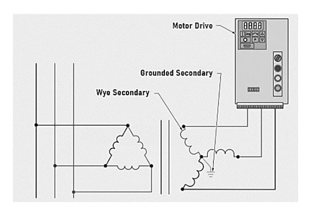
Figure 3. A grounded secondary helps reduce noise and improve power quality
Separately Derived Systems
In contrast to simple line reactors, the secondary of a drive isolation transformer reflects a separately derived system that is electrically separated from the primary source. With the secondary grounded, a transformer wired as a separately derived system acts to prevent the transfer of common-mode noise and transients from the primary source to the drive, as well as from the drive to the primary system.
Electrostatic Shields
Electrostatic shields prevent common-mode noise from moving from the transformer's primary to the secondary only when the secondary is ungrounded. Some experiments have demonstrated that typical noise and transients in industrial systems are best transferred by shielded transformers than those without shields. An electrostatic shield can be helpful if the drive transformer's secondary is not grounded or if a high-resistance ground system is used. However, primary source common-mode noise cannot be induced between the secondary neutral and ground if the secondary of the drive isolation transformer is grounded. An electrostatic shield is not useful under these situations.
Reactors and Drive Isolation Transformers
Reactive control of distorted current harmonics and line notching is provided by both line reactors and drive isolation transformers. However, this is the extent of their similarity (see Figure 4).
Function |
Capacitive Load
|
Inductive Load
|
||
| Reactor | Drive Transformer | Reactor | Drive Transformer | |
| Change Voltage | N/A | Best | N/A | Best |
| Provide Isolation | N/A | Best | N/A | Best |
| Correct line voltage imbalance | N/A | Best | N/A | Best |
| Reduce drive-induced currents | N/A | Best | N/A | Best |
| Reduce common-mode noise | Poor | Best | Poor | Best |
| Reduce line current harmonic injection into primary source | Good | Good | Poor | Poor |
| Reduce source voltage notching | N/A | N/A | Good | Good |
| Reduce feeder short-circuit capability | Best | Good | Best | Good |
| Meet line impedance requirement | Best | Good | Best | Good |
Table 1. A reactor and a drive isolation transformer perform different functions. A reactor is best at controlling line reactance and controlling short-circuit current flow. A drive isolation transformer is best at isolation, voltage control, and noise reduction
Drive isolation transformers offer extra advantages over reactors since their wye-connected secondary can be grounded. This helps protect the motor drive system from common-mode transients originating from the primary source. Drive isolation transformers also shield the primary source from common-mode energies produced by the motor drive system. Furthermore, separately grounding the transformer secondary prohibits ground current from transferring back through the primary ground system.