Facebook
 Google
 GitHub
 Linkedin
Test Lights for Voltage Indication
Learn how to use a test light to find when voltage is present in a circuit.
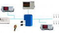
A test light is a test instrument with a bulb connected to two test leads to provide a visual indication of when voltage is present in a circuit. The most common test light is a neon test light (see Figure 1). A neon test light has a bulb that is filled with neon gas and uses two electrodes to ionize the gas (excite the atoms). Neon test lights are preferred because neon bulbs have extended lifetimes compared to other bulbs. The long life of neon bulbs is attributed to the bulbs having a very high resistance, so neon bulbs draw very little current when taking a measurement. The bulb of a test light illuminates when voltage is present in the circuit being tested.

Figure 1. Test lights provide a visual indication of when voltage is present in a circuit but do not indicate the amount of voltage. Image courtesy of Spruce
Test Light Advantages/ Disadvantages
Test lights have the advantage of being inexpensive, small enough to carry in a pocket, and simple to operate. The disadvantage of test lights is that test lights support a limited voltage range and also cannot determine the actual voltage of a circuit; only that voltage is present in a circuit. Test lights that have a wider voltage range are better than test lights that have only one voltage rating. For example, a neon test light rated for 90 VAC to 600 VAC is better than a test light rated for only 120 VAC. Another disadvantage of neon test lights is that neon test lights must not be used to test ground fault circuit interrupters (GFCIs) or ground fault interrupters (GFIs) because the neon bulb does not draw enough current to trip the GFCI when connected between the hot side of the receptacle and ground.
Test Light Applications
Test lights are primarily used to determine when voltage is present in a circuit (the circuit is energized), such as when testing receptacles. When a receptacle is tested, the test light bulb illuminates when it is energized (see Figure 2).

Figure 2. A test light (bulb) illuminates when a receptacle is energized. Image courtesy of Spruce
When a receptacle is properly wired, a test light bulb will illuminate when the test light leads are connected from the neutral slot to the hot slot. A test light bulb will also illuminate when the leads are connected from the ground slot to the hot slot. If the test light illuminates when the leads are connected from the neutral slot to the ground slot, the hot (black) and neutral (white) wires are reversed. Having the hot and neutral wires reversed poses a safety hazard and must be corrected.
If the test light illuminates when the test leads are connected to the neutral slot and the hot slot but do not illuminate when they are connected to the ground slot and the hot slot, the receptacle is not grounded. When a test light illuminates but is dimmer than when connected between the neutral slot and hot slot, the receptacle has an improper ground (having higher resistance). An improper ground poses a safety hazard and must be rectified.
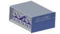
Testing receptacles is also possible with a receptacle tester. The receptacle tester is a device plugged into a receptacle in order to determine if it is correctly wired and energized (see Figure 3). Some receptacle tester models include a ground fault circuit interrupter or ground fault interrupter test button that allows the receptacle tester to be used on GFCI or GFI receptacles.

Figure 3. The receptacle tester is plugged into a receptacle in order to determine if it is correctly wired and energized. Image used courtesy of Amprobe
Note:
Always wear proper protective equipment when working around energized circuits—exercise caution when testing voltages over 24 V.
Test Light Measurement Procedures
Before using a test light or any voltage measuring instrument, always check the test light on a known energized circuit that is within the test light's rating to ensure that the test light is operating correctly.
Before taking any measurements using a test light, ensure the test light is designed to take measurements on the circuit being tested. For all measuring precautions, restrictions, and procedures, consult the test instrument's operating manual. To test for voltage using a test light, apply the following procedures:
1. Verify that the test light has a voltage rating higher than the highest potential voltage in the circuit. Care must be taken to guarantee that the exposed metal tips of the test light leads do not touch fingers or any metal parts not being tested.
2. Connect one test lead of the test light to one side of the circuit or ground. When testing a circuit that has a neutral or ground, connect to the neutral or ground side of the circuit first.
3. Connect the other test lead of the test light to the other side (hot side) of the circuit. Voltage is present when the test light bulb illuminates. Voltage is less than the rating of the test light when the test light is dimly lit and is higher than the rating of the test light when the test light glows brighter than normal. Voltage is not present in a circuit or present at a very low level when a test light does not illuminate.
4. Remove the test light from the circuit.
Note
When a test light does not illuminate, a voltage can still be present that could cause an electrical shock. A test light can be damaged during testing by too high a voltage, so always retest a test light on a known energized circuit to verify that the bulb of a test light that indicated no voltage is still operating correctly.