 Facebook
 Google
 GitHub
 Linkedin
Substation Shielding Methods for Lightning Strikes
This article explains different substation shielding techniques used to reduce the chance of and damage from direct lightning strikes.
Direct lightning strikes to transmission lines or substations may damage the electrical equipment and threaten any nearby personnel.
This article focuses on the current lightning interception methods that engineers use to protect substation equipment and people from lightning flashes. Note that this article specifically looks at protection from direct strikes.
Substation Characteristics
Substations typically consist of:
- Incoming and outgoing overhead lines
- Buses
- Circuit breakers
- Switches
- Transformers (power, current, and potential)
- Auxiliary equipment (such as carrier-current capacitors)
- Buildings
Steel structures support the line terminations, buses, and switches. The steel structures, circuit breakers, and power transformers lay on concrete foundations buried below grade.
Such substations should be protected from direct lightning strikes and from traveling waves arriving through the overhead lines. The purpose of grounding for lightning protection is to provide a secure and certain path for conducting lightning surges to Earth, protecting people and facilities.
Lightning Interception Methods
The main methods to protect substations from direct lightning strikes are:
- Protective angle and protective zone
- Electro-geometrical
- Rolling sphere
- Mesh
Let’s look at each of these methods in detail.
The Protective Angle and Protective Zone Method
Employed for shielding power lines and substations for many years, the protective angle and protective zone method gives reasonable protection. Until recently, it was the method recommended by lightning protection standards.
The method consists of shielding by overhead ground wires, masts, or rods (Franklin’s rods). The ground wires run over the substation so that all equipment lies in the protected zone. The ground wire’s protective angle is between a vertical line through the ground wire and a diagonal line connecting the ground wire and the object to protect, as shown in Figure 1.

Figure 1. Ground wire’s protective angle α.
The ground wire’s protective zone is the volume between the base plane cbc and the diagonal planes ac, extending from the ground wire to the object’s plane. Figure 2 shows a cross-section of this volume.

Figure 2. Cross-section of the ground wire’s protective zone.
From Figure 2, the protective ratio is k=ky/y and the protective angle is α = tanˉ¹k.
Likewise, Figure 3 shows a cross-section of the protective zone for a mast or rod of height = y. In this case, we say that there is a protective cone around the mast or rod. As before, the protective ratio is k=ky/y and the protective angle is α = tanˉ¹k.

Figure 3. Cross-section of a mast or rod protective cone.
Over the years, many researchers have worked to determine the best figures for the protective ratio and the protective angle. Table 1 shows typical values still employed.
Table 1. Typical Value Employed for Protective Ratio and Angle
| Protective ratio |
Protective angle α (Degrees) |
| 1:1 | 45 |
| 2:1 | 63.5 |
| 0.58:1 | 30 |
The designers allow a reduction of the angle as the protective device – ground wire, mast, or rod – height increases because those angles may be inadequate for tall structures.
The size, shape, and quantity of objects to protect establish the total number of grounding wires, masts, or rods to install. Protective devices should be sufficient to cover the entire substation, including the apparatus outside and on the main structure’s top. The overlapping of the protective zones decreases the likelihood of direct impacts (Figure 4).

Figure 4. Overhead ground wires protect the substation.
The grounded steel structure is enough to shield the buses and apparatus below it when there are no objects to protect above the substation’s top.
In small substations, masts or rods erected at the corners or columns shield the buses and apparatus falling within their protective cones (Figure 5). Another arrangement employs self-sustaining masts inside and next to the substation.

Figure 5. Vertical masts protect the substation.
The ground wires, masts, and rods must be connected to the substation’s grounding electrode and the overhead lines’ counterpoise system if any.
The ground wires of the incoming and outgoing overhead lines should terminate at the top of the substation’s steel structure — this might require steel columns extending above the main structure. For unshielded lines, the recommendation is running a ground wire for a distance of at least 1 km to reduce the magnitude of the lightning surges entering through the lines.
The Electro-Geometrical Method (EGM)
In the early 1970s, the electro-geometrical method was used to shield power lines from lightning. Later on (around 1976), its use was broadened to include substations.
The striking distance is a crucial concept for understanding the electro-geometrical method.
According to the stepping mechanism’s prestrike theory, before the stepped leader reaches the ground, a discharge similar to the leader rises from the ground to meet it. After the stepped leader establishes a ground connection, a power return strike moves up the ionized channel prepared by the leader.
The EGM theory states that when the stepped leader reaches a critical distance from a grounded structure where the average potential gradient in the gap between the leader tip and the grounded structure is equal to the streamer’s potential gradient, the gap breaks down, attracting the lightning flash to the grounded structure. This critical distance is the striking distance.
In the case of taller structures, the striking distance is the interval from the leader tip to the structure when a streamer is initiating on it.
The first element on a grounded structure within striking distance will be the point of the strike of the lightning flash. The striking distance depends on the return strike peak current; the higher the strike’s current, the greater the striking distance and vice versa.
An important concept is that the shielding system design assumes a strike current of magnitude I1. The resultant shielding might not protect the objects for strike currents I2 < I1 with a shorter striking distance, but will likely guard the items for strike currents I3 > I1 with a more considerable striking distance.
The substation’s shielding intercepts strikes of magnitude I1 or higher. Then, the substation insulation must withstand the resulting voltages, without flashover, when strikes with currents less than I1 in magnitude penetrate the shielding. Setting the design strike current by considering what the system insulation can withstand ensures that the substation will be protected when impacted by strikes with the lower current.
Not all the strikes with peak currents less than I1 will defy the shielding and strike the structures. Depending on the location of the stepped leaders, the shielding will capture some of these strikes.
The Rolling Sphere Method
The rolling sphere method is a derivative of the electro-geometrical method. It uses a fictitious sphere of radius S to locate the lightning protection devices on structures. The term rolling sphere derives from Ralph H. Lee’s studies in the USA (1977) for shielding buildings and industrial plants.
The method starting point is the existence of a spherical volume with a radius equal to the striking distance, positioned around the stepped leader’s tip. The stepped leader will attach to the first point of a grounded structure entering this volume.
The sphere should touch only the protection system elements when it is rolled around the protected structure. Where the sphere touches the equipment or buildings in the substation, lightning strikes are a hazard. In the space between the sphere and ground, lightning is improbable.
Figure 6 shows a tall structure and a rolling sphere of radius S. All points touched by the sphere are unprotected, which shows us that the roof and sections of the walls require shielding.

Figure 6. Sphere rolling over a tall structure.
Figure 7 shows the same sphere with a lower structure. Here, only the roof requires shielding.

Figure 7. Sphere rolling over a low structure.
In a substation, the sphere rolls up and over ground wires, masts, rods, fences, and any grounded metallic object to be protected (Figure 8).

Figure 8. Principle of the rolling sphere method with multiple shielding electrodes. Image from IEEE Std 998.
Figure 9 shows a sphere of arbitrary radius rotating over equipment and a mast in a substation section. Notice the unprotected portions of equipment inside the sphere.

Figure 9. Sphere rolling over equipment and a mast in a substation uncovers unprotected spots. Image based on Verdolin Solutions.
If we recall that the sphere radius – the striking distance – depends on the projected return strike peak current, and that there is less protection for lower currents, the shielding of structures sensitive to lightning strikes should use small currents and small sphere radius as design criteria.
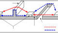
The rolling sphere method allows us to determine the protective cone and the equivalent protective angle of a mast or rod. Figure 10 shows the protective cone (the shaded region wraps around the device) and the equivalent protective angle for two vertical masts using a sphere with a 20m radius. Note that the protective cone and angle figures depend on the device’s height for a constant sphere radius.

Figure 10. Protective cones and angles resulting from the rolling sphere method. (a) Low mast (b) tall mast.
The rolling sphere method applies equally to flat surfaces, sharp points, edges, and corners. This condition is the method’s drawback because field observations on buildings show that most strikes finish on sharp points or projecting corners. Research indicates that the connection of lightning strikes to the structures depends on the prospective return strike peak current and the structure’s geometry. This limitation in the method may cause errors under some circumstances.
The Mesh Method
The only way to make a structure lightning-proof is by enclosing it in grounded metal (Faraday cage), but this solution is not practical. The mesh method consists of enclosing the structure within a conducting mesh, attaining a practical Faraday cage. This method is useful for shielding a substation’s buildings, like the control room.
The method locates a mesh of wires on the top or at a certain distance from the building’s roof and provides down conductors for connection to the grounding electrodes. The cell size and the separation between down conductors depend on the protection level required. Most lightning currents go through the wires and grounding electrodes close to the impact point.

Figure 11. Wire mesh on the top of a building. Image based on Aplicaciones Tecnológicas.
The rolling sphere method confirms the cell dimensions for different levels of protection. Figure 12 shows that, according to the rolling sphere method, lightning can strike the building with the mesh resting directly on the roof. Thus, it is better to allow some clearance between the mesh and the building top.

Figure 12. Raising the wire mesh increases the building’s protection.
A Review of Substation Shielding
The protection of a substation against direct lightning strikes consists of providing secure conducting paths to carry the lightning currents to the ground without damaging equipment and jeopardizing personnel.
The oldest and most straightforward method is the protective angle and protective zone. It uses the protective angle for the location of grounding wires, masts, and rods. The angle α describes an inclined line that limits the protective zone. The structures located within the protective zone are significantly safe from lightning strikes.
In the case of a ground wire, the protective angle results in inclined plane surfaces below which all objects have protection against the lightning strikes. For masts or rods, the protective angle generates a conical surface protecting items below it.
The protection may not be complete if the equipment is beyond the device’s protective zone. Some of the strikes may hit the equipment or people rather than the protective device in such cases.
The protective angle and protective zone concept is rather old-fashioned, and methods have evolved to make protection more accurate. One of these methods is the rolling sphere.
In this method, a sphere is rolled over the protecting structure, and the areas which the sphere cannot touch are within the protective zone. The radius of the sphere depends on the striking distance. The striking distance is the length over which the lightning strike’s final breakdown to ground or a grounded object occurs. Higher levels of protection are achieved when the design of the protection system is based on a sphere of reduced radius.
Currently, the rolling sphere method is widely accepted.
A horizontal conductor network is often used as a protective system on structures with a flat roof, as a means of achieving an effect similar to that of a Faraday cage. This technique is the mesh method. The mesh method places the conductors on the building’s roof and connects them to the ground through down conductors that offer a short conducting path to the earth. The mesh provides multiple ways for the lightning current to flow to the ground.


Brilliant article Lorenzo…!!!
You have cover all the topics related with this important knowledge area of the Power Substations Design with the highest professional level proper of an experienced Electrical Engineer like you.
I wish you the Best Success in this valuable activity of the engineering.
Best Regards,
Angel Machado