Facebook
 Google
 GitHub
 Linkedin
Solving the Voltage Drop Problems of Industrial Power Lines
This article highlights Analog Devices, Inc. LT8710 DC-to-DC controller that supports synchronous SEPIC, boost, and inverting converter topologies.
The LT8710 is a versatile DC-to-DC controller that supports boost, SEPIC, inverting, or flyback configurations, and is widely used in automotive and industrial systems. It includes features that enable use in applications with high impedance power supplies, or where input current must be limited. For example, long power lines in industrial plants and warehouses add significant input source resistance, as well as a significant voltage drop from converter to load.
This value can change as equipment is relocated, further complicating regulation. Solar panels also have a high impedance input, with a peak power output and a narrow voltage range. This design note demonstrates how the LT8710 can solve the problems of high impedance and current limited input sources, through the example of a lithium-ion battery charger.
Circuit Description and Functionality
Figure 1 shows a charger solution for a 20 V lithium-ion battery commonly used in portable power tools. The voltage source, VSRC, is 24 V via a high impedance power line, resistor RLN, resulting in the voltage VIN at the charger input terminals. The voltage source could be considered as a popular 12 V solar panel with 22 V to 24 V open-circuit and 18 V to 19 V optimum operating voltage. The charger is based on a synchronous, noncoupled SEPIC topology and controlled by the LT8710. The power train consists of discrete inductors L1, L2, transistors Q1, Q2, decoupling capacitors between the inductors, and input/output filters. Resistor RSC sets 2 A of charge current, ICHRG; resistor RV(FL) sets the float voltage of 21 V. The resistor divider RIN1/RIN2 sets input voltage regulation level, which is 18.6 V in this example
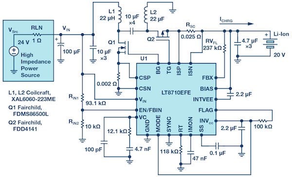
Figure 1: Electrical schematic of a LT8710 lithium-ion battery charger in high impedance input lines.
Figure 2 illustrates the functionality of the charging solution over time. When VIN and power source voltage VSRC are above 19 V, the LT8710-based SEPIC charges the lithium-ion battery to the programmed 2 A, ICHRG. As VSRC drops below 20 V, the value of VIN drops correspondingly. When VIN reaches the input voltage regulation level, the LT8710 reduces the charging current, ICHRG, to maintain
VIN, even as VSRC continues to decline. The horizontal axis represents normalized time, which can be hours for a solar panel, or minutes, or seconds, for power supplies in complex industrial systems.
Another way to control the load for converters based on the LT8710’s
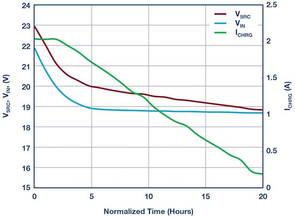
Figure 2: Charging current (ICHRG) as a function of the voltages power supply (VSRC) and charger input terminals (VIN).
input current is to monitor voltage of the capacitor from the IMON pin. Select resistor RSC to provide a voltage close to 50 mV at the maximum current. A corresponding voltage is reflected across the IMON capacitor. If there is no current flow and the voltage across the ISP and ISN pins is zero, then the IMON voltage is approximately 0.616 V. If the ISP–ISN voltage is 50 mV, it reflects the IMON voltage as 1.213 V. This feature, as well as many others, can be evaluated using our demonstration circuit DC2067A and corresponding LTspice® models.
Conclusion
The LT8710 is a versatile and flexible controller that supports synchronous SEPIC, boost, and inverting converter topologies. Along with a wide range of input voltages and switching frequencies, it includes advanced features, such as the ability to regulate the input voltage and output current based on input current or voltage. These features make the LT8710 ideal for industrial, solar panel system, and other current limited applications
About the Author
Victor Khasiev is a senior applications engineer at ADI. Victor has extensive experience in power electronics both in ac-to-dc and dc-to-dc conversion. He holds two patents and has written multiple articles. His patents are about efficient power factor correction solutions and advanced gate drivers. Victor enjoys supporting ADI customers: answering questions about ADI products, the design, and verification of power supplies schematics, and the layout of the print circuit boards; troubleshooting; and participating in testing final systems.
This article originally appeared in the Bodo’s Power Systems magazine.