Facebook
 Google
 GitHub
 Linkedin
Properly Validating Output Chokes: Ferrite vs. Dust Core
For the emerging mega-watt applications with SiC power devices, the proper validation of output chokes poses great challenges.
Output chokes for Switched Mode Power Supplies (SMPSs) normally operate for a DC load, where a bias magnetic field (HDC) is generated under operation of the magnetic cores. For the emerging mega-watt applications with SiC power devices, the proper validation of output chokes is of great challenge. Basically, there are two criteria for magnetic component design, which are from the thermic aspect or from the magnetic nature.
These two criteria couple and the difficulty of proper validation is enhanced by the ever-increasing requirement of high efficiency, high-power density, as well as additionally by the system reliability.
Standards for magnetic materials validation do exist but only specified by voltage levels, whereas the standards by power levels are still lack. However, the increasing requirement for proper validation comes up with developing applications, including the shipboard medium voltage distribution and propulsion, chargers for electric vehicles, medium voltage grid-tied interface for data center and hybrid propulsion for future aircraft. In these applications, power levels can range from hundreds of watts to hundreds of megawatts [1].
Since no micro-magnetic model for magnetic material exists, which is able to lead an analytic reveal of the nonlinearity for magnetic components, measurement is now regarded as the only way to address the challenge. The impulse technique, with its transient high current amplitude to characterize the saturation behavior, and elimination of the thermal effect during the measuring period, becomes the only option. The damped oscillation with full reversal current, enabling power loss evaluation, is very promising, to be established as a validation standard.
Using this concept, a measurement configuration with a bipolar thyristor (SCR silicon-controlled rectifier), which can endure high voltage stress and high dU/dt, has been reported and it is able to provide an accurate validation and loss measurement for critical applications [2]. In this article, a comparative study for a high-saturation material D9BTM vs. dust core design with same design and nominal parameters is made and validated for its advanced performance for higher power applications.
Design Challenges for Output Chokes
The saturation is an intrinsic phenomenon of magnetic materials, magnetic cores, and components, and it is the main concern for designing the output chokes in SMPSs. Typically the power ferrite materials start to saturate when the magnetic field strength achieves 50 A/m and also the permeability of the materials drops sharply. The saturation can be directly observed by measurement and can be qualified by derived differential inductance, amplitude inductance and energy equivalent inductance [2]. The need to highlight is that all the features can be measured by the pulse method, which can also avoid thermal interference by heat dissipation during the measurement.
Conventionally there are two remedies against the saturation effect in the magnetic design:
- The use of gapped ferrite cores
- The use of metal alloy powdered cores
In the case study, we tested both configurations with the gapped ferrite cores in D9BTM material and the alloyed powered cores (super sendust powdered core) in the same shape. The new high Bs ferrite materials, which feature a higher saturation level as well as a high Curie temperature, especially at elevated temperatures, have been reported by [3] [4]. The D9BTM material owns a high saturation feature, whose saturation flux density is higher than 600 mT at room temperature and higher than 500 mT at 100 °C. Besides, its Curie temperature is over 320 °C (i.e. 600 Kelvin), which makes it highly adaptable for higher power applications. The physical configuration for two cases was designed identical to provide a fair comparison: the core shapes are standard E65/ 32/ 27 and the effective permeability of the D9BTM cores were controlled the same as well by gapping properly, and the winding configuration was also built identically. Thus, the only difference between the two cases is the materials and the gapping configuration.
Materials Performance Evaluation with Outerdiameter 1-inch Ring Cores
As to the evaluation of magnetic components, where the current standard IEC 62024 is only valid till rated current of 22 A [2], standards for magnetic component for high current application is still missing. The ferrite material evaluation has been standardized by IEC 62044. In more detail, the description of nonlinearity is distinguished in two categories: the small-signal measurement is specified in IEC 62044-2, in which the initial permeability, temperature coefficient, etc. are defined; and the large-signal measurement is specified in IEC 62044-3, which includes amplitude permeability and its corresponding loss.
In this study, we aim to qualify both the performance of the materials and of the components for the reluctance-level-modeling. For example, the amplitude permeability of the material and its temperature dependence can be measured for evaluation and circuit-level simulation.
The large signal parameters (i.e. amplitude permeability and core loss) for D9BTM and super sendust material are listed in Tables 1 and 2, where the measurement is performed according to IEC62044-3 by BsT-Analyze. Those data are performed at different temperature level, and only the flux density dependence for particular frequency and temperature is shown:
Table 1: Tested parameters for D9BTM ferrite material at 25°C/ 16 kHz
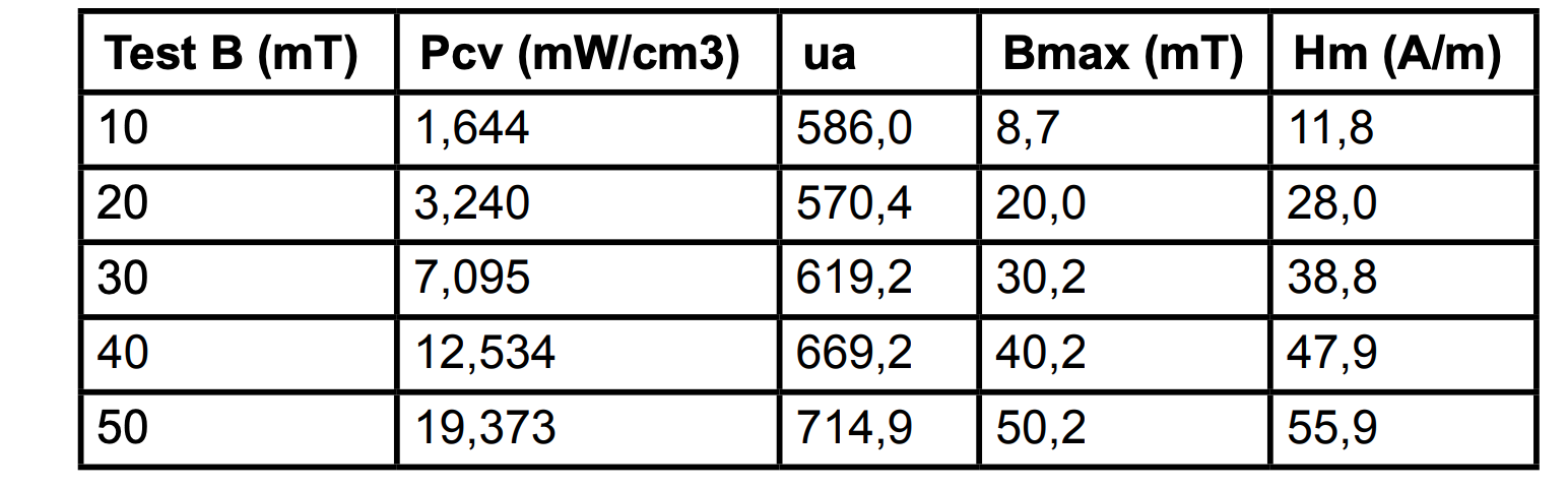
Table 2: Tested parameters for super sendust powder material at 25°C/ 16 kHz
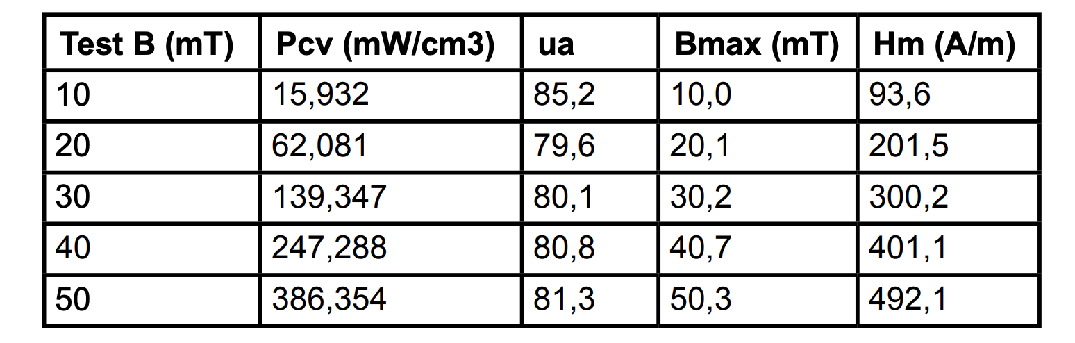
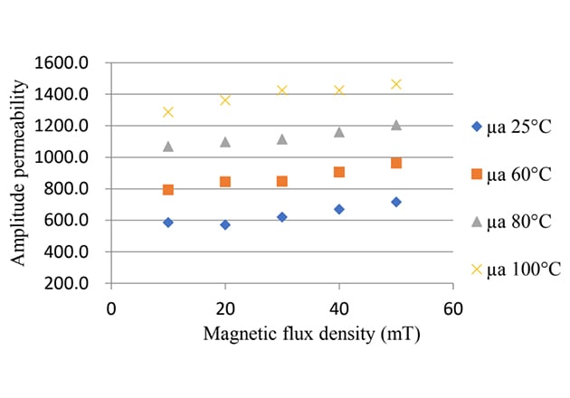
Figure 1: Amplitude permeability vs. flux density for ferrite D9B™ material
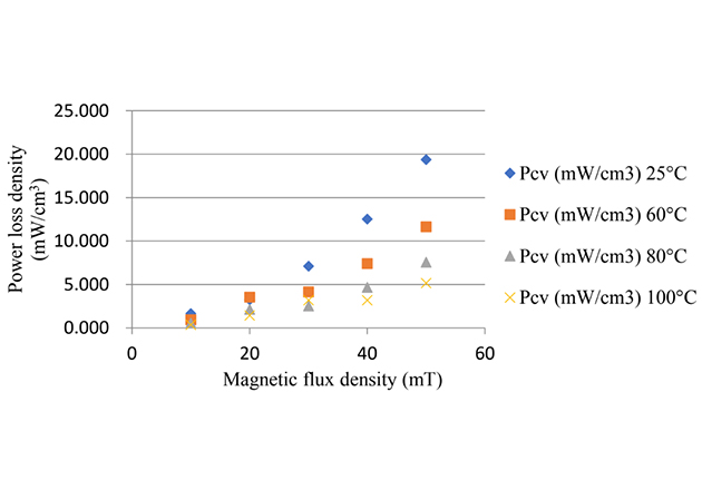
Figure 2: Power loss density vs. flux density for ferrite TM material D9B™ material
It can be noticed from the measurement that the super sendust material shows higher thermal stability by the large signal parameters: the amplitude permeability and the power loss are significantly less dependent on the temperature (Figures 3 and 4). In addition, the power loss measurement results reflect that the magnetization current would be higher than that in ferrite materials by an order, thus giving a low permeability at a constant frequency and flux density. Compared to previous power ferrite materials, such as N92, 3C92, and PE90, D9BTM provides obviously more accessible flux linkage at 100°C as an inductor for energy storage during magnetization, because it has higher saturation flux density Bs, which can be over 600 mT in room temperature and over 500 mT at 100°C [4].
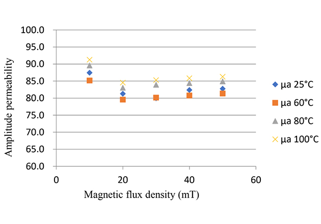
Figure 3: Amplitude permeability vs. flux density for super sendust material

Figure 4: Power loss density vs. flux density for super sendust material
Evaluating the Component with Gapped Ferrite Core Design vs. Dust Core:
During the operation of the output chokes, the magnetizing and de-magnetizing process by large energy excitation would repeat continuously thus a fair evaluation must be conducted by large-signal measurement. In this case, the small-signal testing would lose accuracy while the pulse method shows its benefit of enough power excitation and no thermal interference, because of very short term excitation.
Firstly, the devices are tested by the small-signal method: the series inductance is measured as 36 µH and the equivalent series resistance is measured as 450 mΩ. The measurement equipment is Agilent 4284A and the excitation is 1 kHz/ 20 mA. The photo of the tested component with super sendust material is shown in Figure 5.

Figure 5: Photo of tested compoment with super sendust material
The large signal measurement is conducted by BsT-Pulse, whose operation is illustrated in Figure 6. In the first subinterval, the capacitor C is charged to a specific voltage, which is depended on the value of pulse energy and on the second subinterval, the energy is damped by the Device Under Test (DUT) in a temperature chamber, together with a capacitor, during which the voltage and current of the damping circuit should be sampled for further evaluation. In the case study, the capacitor was charged to 100V and then damped by the tested components with E65/32/27 cores. The damping voltage and current for both the D9BTM ferrite core (left) and super sendust core (right), as in Figure 7. Compared with other measurement set-ups, such as continuous sinusoidal excitation, the major advance of the pulse method is that the thermal interference during the testing can be eliminated maximally. Thus, as illustrated the performance of the materials or the components can be depicted as a function of temperature.
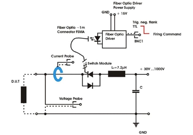
Figure 6: Illustration of pulse method testing for BsT-Pulse
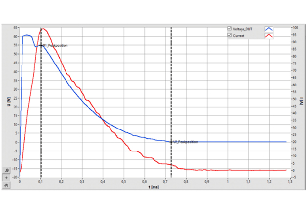
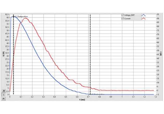
Figure 7: Damping record for pulse testing in BsT-Pulse (100 °C; voltage in blue, current in red)
The magnetizing and de-magnetizing can also be depicted by the pulse method because the pulse process consists of two sections: Section 1: Magnetizing process of the measuring object from I = 0 A to I = Imax, Section 2: Demagnetizing process of the measuring object from I = Imax to I = 0 A. The amplitude inductance, which is defined as
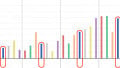
which is able to depict the key performance for an output choke, including the saturation phenomenon and the nonlinearity under different excitation. In Figures 8 and Figure 9, the amplitude inductance during the magnetizing and de-magnetizing process for the component with ferrite D9BTM core is illustrated. Correspondingly the amplitude inductance of the component with the dust core is illustrated in Figure 9 and Figure 10. It can be noticed in the component with D9BTM core that when the excitation current increases higher than 65A, the saturation phenomenon comes up, thus the corresponding amplitude inductance starts to decrease during the magnetizing process. As a comparison, during the de-magnetizing process, the saturation disappeared also at 65A excitation but the performance shapely shift under low excitation, which is more obvious at 20 °C environment. This detailed depiction of the performance advances other measurement methods and is capable of expanding at mega-watt applications, which cannot be conducted by the conventional method.
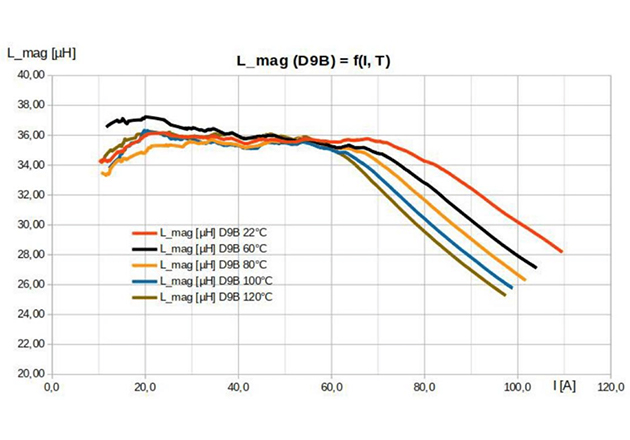
Figure 8: Amplitude inductance of the component with D9B™ material v.s. current during magnetizing process
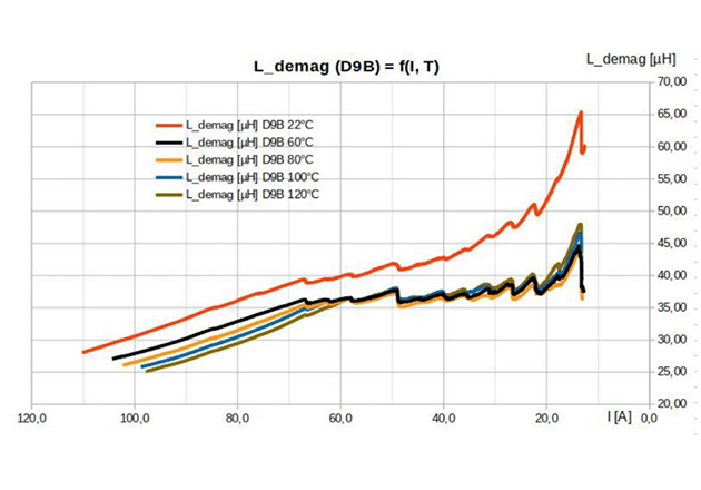
Figure 9: Amplitude inductance of the component with D9B™ material vs. current during de-magnetizing process

Figure 10: Amplitude inductance of the component with dust material vs. current during magnetizing process
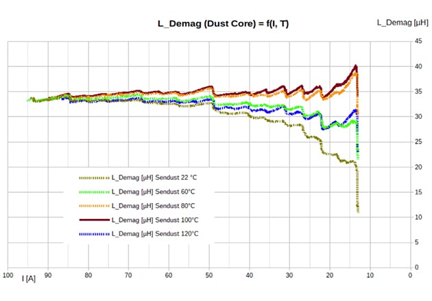
Figure 11: Amplitude inductance of the component with dust material vs. current during the de-magnetizing process
The enveloped area through magnetization and demagnetization equals energy loss of choke in half cycle, and this can be calculated by the bipolar impulse method. The flux linkage vs. magnetization current at different temperatures is illustrated, here again, the accessible working flux linkage of ferrite design is significantly dependent on temperature compared to powder core design in Figure 12. The core loss of the D9BTM and the dust core can be calculated by integral of the enveloped area.
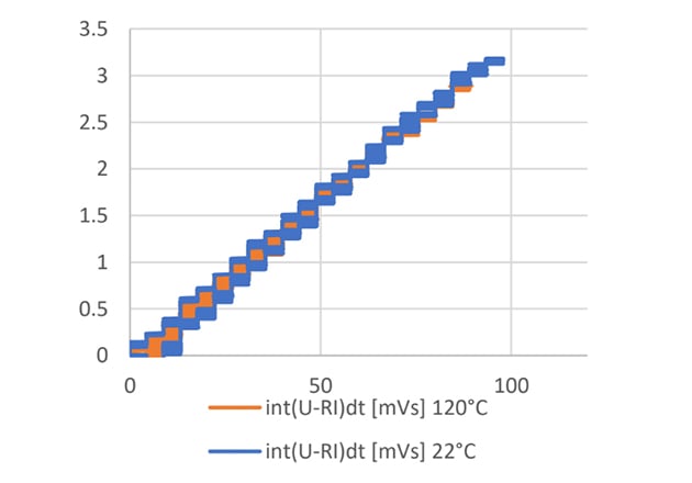
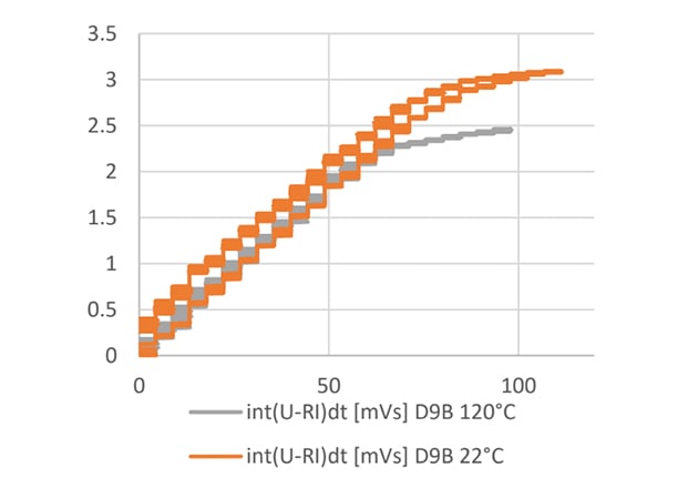
Figure 12: flux linkage vs. magnetization current comparison with D9B™ (on left) and dust core (right) material for 22°C and 100°C
The conventional design approach for output chokes is to calculate effective permeability through the ratio of air gap length to the effective magnetic path length due to the air-gap actually dominates the energy stored inside of the magnetic circuit. The reluctance of air gap needs to be controlled and overcome to reach desired current amplitude. Under these circumstances, the analysis of the fringing effect becomes more challenging because both the geometry and the flux distribution need to be understood thoroughly [3]. However, the detailed comprehension of the loss mechanism is still missing thus the importance of measurement should be truly valued.
Nowadays the specification of a magnetic component with a defined shape, air gap length, and winding topology is uniquely assigned to manage the procurement, but it still does not deliver necessary magnetic property, which urgently needed by application engineers. The performance uncertainty becomes increasingly critical for wide acceptance for energy transformation, especially for emerging power range.
Conclusion
The design of gapped ferrite core E62/32/27 are studied along with super sendust powdered core and a complete inductance analysis by the pulse method at different operation temperatures is presented. This study provides insight magnetic properties under pulsation condition, which is able to decouple the self-heating disturbance. Comparing conventional small AC signal measurement with the unipolar impulse technique, the bipolar impulse technique, with a damped oscillation approach is able to provide the full picture of the nonlinearity of inductor performance, and loss evaluation, decoupled with thermal interference. The bipolar damped oscillation method shows great potential, especially the new configuration; equipped with thyristor stack for medium voltage level (tens of Kilovolt), with a repetition rate of some kHz, is the target for 3 phase power reactor of future emerging megawatt power applications.
About the Authors
JC Sun is the founder of Bs&T Frankfurt. During the first two decades of his career, he was a development engineer for power electronics focused on the development of various soft magnetic materials.
Yi Dou is a Ph.D. student focusing on Power Electronics and has strong background in high-frequency DC-DC converter and magnetic design. The topic of my PhD project is Advanced Power Converter in Wireless Power Transfer (WPT) system. He is skilled in the field of research, magnetic device design and LTSpice simulation.
References
-
J. Wang, "Challenges Facing Emerging Megawatt Applications: New Technology and Solutions Needed for High-Power Applications," in IEEE Power Electronics Magazine, vol. 6, no. 4, pp. 38-40, Dec. 2019.
-
J. C. Sun, “Proper Specification of Magnetic Components”, Bodo’s Power Systems, pp. 36–39, Dec. 2019.
-
E. C. Snelling, Soft Ferrites Properties and Applications. Butterworth & Co, pp. 143-144, 1988.
-
J. C. Sun, "Recent Development in Ferrite Material for High Power Application [Passive Components]," in IEEE Power Electronics Magazine, vol. 5, no. 3, pp. 21-25, Sept. 2018.