Facebook
 Google
 GitHub
 Linkedin
Power Transformer Basics: The Magnetic Circuit
Learn about the magnetic circuit underlying the performance of transformers, and the equivalent model to properly analyze their operation.
A transformer is an electromagnetic device for transferring electric energy from one circuit to another magnetically. A transformer is usually employed to transfer energy between circuits of different voltages. There are two or more windings in a transformer's magnetic core. The transformer is a vital link in industrial and commercial electric power systems and an essential component in many low-power applications, such as control systems and electronic circuits.
Power Transformer Principles
Transformers are static devices that transfer energy from one set of coils to another through a varying magnetic flux, provided that both sets are on a common magnetic circuit (core). A change in the magnitude of flux linkages with time induces electromotive forces (Figure 1).

Figure 1. Elementary transformer, secondary open circuited
Rectangular stampings of magnetic sheet steel, clamped together, make up the transformer core. Copper or aluminum windings positioned on the core (or the legs) comprise the primary, secondary, and tertiary of the transformer.
Usually, we would name the power receiving side the primary side and name the power delivery side the secondary side. Tertiaries, when used, have diverse purposes.
We can also identify the windings according to the voltage: high-voltage side (HV), and low-voltage side (LV). This approach is practical when power flows in both directions.
The ratio of transformation, or turns ratio, depends on the relative number of turns in each winding. It is also the ratio of the primary to secondary no-load voltage, or voltage ratio. Under load conditions, the actual voltage ratio is a little different due to the drop in the transformer windings. A transformer’s voltage regulation refers to this drop at rated load, which varies with the load power factor, even with constant kVA (kilovolt-ampere).
When the voltage is increased or decreased by the transformer turns ratio, the opposite happens to the current. The product of voltage and current on each side is the same. In the ideal transformer:
E1 · I1 = E2 · I2
Turns ratio N = N1/N2 = E1/E2 = I2/I1
E2 = 1/N · E1 and I2 = N · I1
A key concept to remember is the product of current and number of turns in each winding N·i must balance. This balance is called ampere-turns, although the unit for N·i, according to Ampere's law, is the Ampere.
The Hysteresis Loop and the Normal Magnetization Curve
Materials with a high relative magnetic permeability like steel alloys containing combinations of cobalt, nickel, aluminum, tungsten, and silicon are used to guide the magnetic flux into a region to achieve high energy densities. These are ferromagnetic materials and have a permeability much higher than air.
The operation of many devices depends on the nonlinear characteristics of their magnetic circuits. In other cases, nonlinearity is undesirable because it may distort the waveforms of voltages and currents in alternating current circuits, as we'll see further on.
Figure 2 shows an essential characteristic of ferromagnetic materials — the relationship between the flux density B and the magnetic field intensity or magnetizing force H — for a sinusoidal variation in flux. The value of B, for a given amount of H, depends on whether H is increasing or decreasing. This lag of flux density behind the magnetic field intensity is the hysteresis loop.

Figure 2. Hysteresis loop. Image courtesy of the Virtual Institute of Applied Sciences.
If some hysteresis loops are plotted sequentially for several successively higher values of voltage and flux, each loop completely encloses the preceding one. The dotted curve through the positive tips of the loops, indicated by o-g-h, is the normal magnetization curve shown in Figure 3.
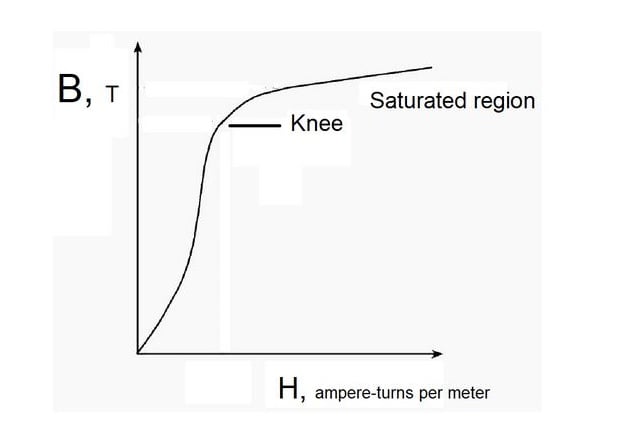
Figure 3. Normal magnetization curve
The flux density Br at H = 0 is the residual magnetic flux density, and the magnetizing force Hc at B = 0 is the coercive force, required to reduce the residual magnetism to zero.
During one complete cycle, the energy supplied to the magnetic circuit is higher than that returned to the source. The area of the hysteresis loop is a measure of real energy loss that appears as heat generated within the material, during one cycle of magnetization.
Large power transformers operate at high flux densities because working with the iron unsaturated requires a large size, increasing costs.
In nonmagnetic materials, such as air, the hysteresis loop becomes a single diagonal straight line through the origin.
Eddy-current loss
The alternating flux causes currents to flow in the core. Eddy-current loss is the power required to sustain these eddy currents, and it manifests itself in the form of heat.
The Exciting Current
The characteristics of iron cores are not ideal because of core losses and finite permeability.
When an alternating current (AC) generator supplies current to the primary winding of an unloaded transformer, its magnetomotive force (MMF) produces an alternating mutual flux (ɸm) in the core. This small current is called the exciting current. Its magnitude is about 3% or less of the full load current.
When the transformer secondary shorts, the current that flows is very high — up to 30 times the full load current.
The exciting current (Ie) has two components: the core-loss current (Ih+e) and the magnetizing current (Im). The core loss is a real-power component, due to hysteresis and eddy currents, revealed as heat generated in the core. The magnetizing current (Im) furnishes the MMF to get over the magnetic reluctance of the core.
The total exciting current is the phasor sum of the two components:
Ie = Im + Ih+e
The phasor diagram in Figure 4 shows that Im is in phase with ɸm. Ih+e, as an energy phenomenon, is in phase with the voltage and leads the magnetizing current by 90°.

Figure 4. Phasor addition of components of exciting current
Leakage Fluxes
A permanent magnet instrument may show pulsations in the area around an energized transformer. A leakage flux that is in the air because it could not link with all the windings on the core, causes the pulsations.
Figure 5 shows, on the left, the leakage flux (ɸ1'), produced by the current flowing in the primary winding turns. The secondary winding leakage (flux ɸ2'), on the right, exists only when the current flow in its turns. Both fluxes link with all turns of their windings but not with the others.
Figure 5. Magnetizing flux ɸm, leakage fluxes ɸ1' and ɸ2' in a transformer.

Figure 5. Magnetizing flux ɸm, leakage fluxes ɸ1' and ɸ2' in a transformer
A significant factor is that there is fundamentally a linear relation between the leakage fluxes and the MMFs (or currents) that produce them. The path of the leakage fluxes is almost entirely through the air and it is a nonmagnetic media.
A Transformer Equivalent Circuit
An equivalent circuit adequately represents a transformer’s behavior. Inductances symbolize the leakage and magnetizing fluxes and resistors, the winding resistance, and core loss.
There are complex and straightforward transformer equivalent circuits. Figures 6 and 7 show models useful to understand the basic concepts discussed in this article.

Figure 6. Transformer equivalent circuit, no-load conditions
Under no-load conditions:
V1 = Ie · R1 + Ie · ω · L1 + Im · ω · Lm = Ie · R1 + Ie · ω · L1 + E1 = Ie · (R1 + jX1) + E1
V1 and E1 have a difference of about 2% to 3% in high-quality transformers, meaning that the leakage impedance R1 + jX1 is quite small. Extra-high voltage transformers may have a difference of up to 12%.
When the transformer delivers a load current, a similar equivalent circuit represents the secondary leakage flux, comprising a secondary inductance (L2) and reactance (X2), as well as the secondary winding resistance (R2) shown in Figure 7.

Figure 7. Transformer equivalent circuit, with load
The secondary induced voltage E2 depends on the turns-ratio,
E2 = N2/N1·E1
At no load,
V2 = E2
When a load current I2 flows in the secondary winding,
V2 = E2 – I2 · (R2 + jX2)
A Review of Transformer Characteristics
A transformer is an electromagnetic machine used to transfer electric energy between two circuits through a varying magnetic flux.
Transformers cores use ferromagnetic materials with a permeability much higher than the air. Their permeabilities vary with the flux density, and a given mmf produces a flux whose magnitude changes. Inside the cores, there are losses due to hysteresis and eddy currents, manifested in the form of heat.
When an AC source energizes a transformer, under no-load conditions, a small exciting current flows generating a mutual flux and heat losses in the core. The exciting current components are the core-loss current and the magnetizing current.
Leakage fluxes link only the windings that produce them.
Equivalent circuits accurately represent transformers to help better understand their behavior.
Related Content