Facebook
 Google
 GitHub
 Linkedin
Power Semiconductor Modules to Support Lower Voltages
This article examines the use of power semiconductors in a low voltage drive with the general architecture.
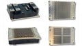
The Front End, also called a line-side converter, converts an AC voltage to DC and supplies it to the DC-Link. Depending on the operating scheme, diodes, thyristors or even IGBTs might be used for this application. Typically products such as Hitachi ABB Power Grids Semiconductors’ 60Pak diode and thyristor modules might be used because they feature industry-standard housings and very low losses together with the highest operating temperatures. This allows these devices to deliver the highest performance under load cycling, high thermal utilization, increased overload capability, and many more benefits.
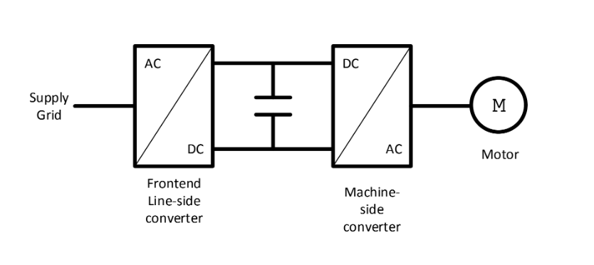
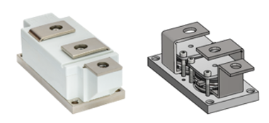
Figure 2: 60Pak BiPolar module
The 60Pak product family has a press-force construction, where is the assembly is pressed by the mainspring to the base plate (cooler) instead of a soldered connection. This construction produces a better performance, particularly improved reliability over the device’s lifetime. The dual spring clamping system helps to achieve impressing IOL (Intermittent Operational Life) performance, longer lifetime and enhanced resistance to temperature changes. The dual spring system consists of the main square spring on the top and a pair of auxiliary springs. This unique setup enables close to ideal efficiency in a well-known hockey puck housing.
In the image below you can see the force distribution of the two spring systems compared with ceramic + metal and plastic insulator force spreaders.
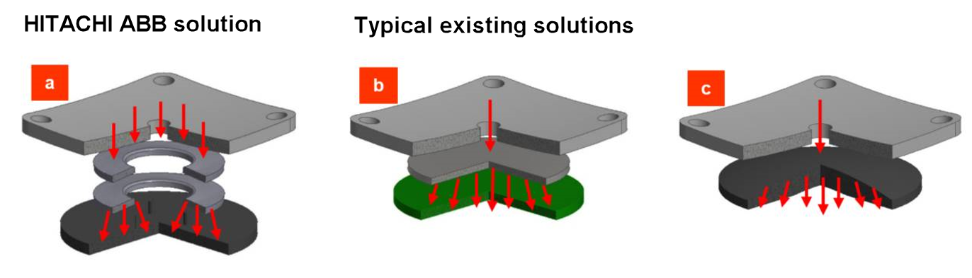
Figure 3. a) Dual spring construction, b) Ceramic + metal force spreader, c) Only plastic force spreader
The modules passed the reliability tests shown below.

The results show that this approach to module design brings the performance and reliability associated with Hitachi ABB Power Grids, medium, and high-voltage devices to lower voltages.
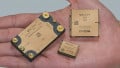
For the active Front End, or machine-side converter, that connects the DC-link to the motor, LoPak modules are a popular choice. These LoPak modules are now available for 1200 V voltage class systems, and with pre-applied TIM (Thermal Interface Material) that helps to increase reliability over the drive’s lifetime.
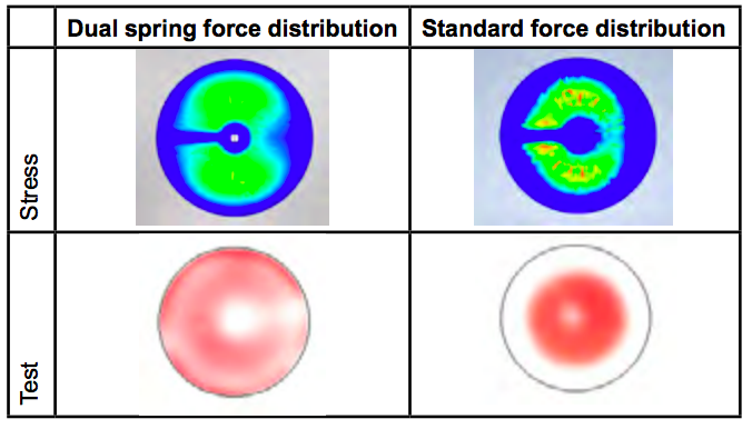
Figure 4. Comparison of standard force distribution with dual spring force distribution
Even at lower voltages, engineers not only want to create new inverter designs but would also like the ability to upgrade their existing designs to handle higher power using the same module package. This allows a faster time-to-market, less disruption of manufacturing lines, and potentially lower unit costs.
Building on its experience of high-performance, high-reliability devices for voltages above 3.3 kV, Hitachi ABB Power Grids has expanded its product portfolio by introducing a family of 1200 V power modules to complement the existing 1700 V family, starting with a 1200 V, 900 A x 2 module using an upgraded LoPak module package.
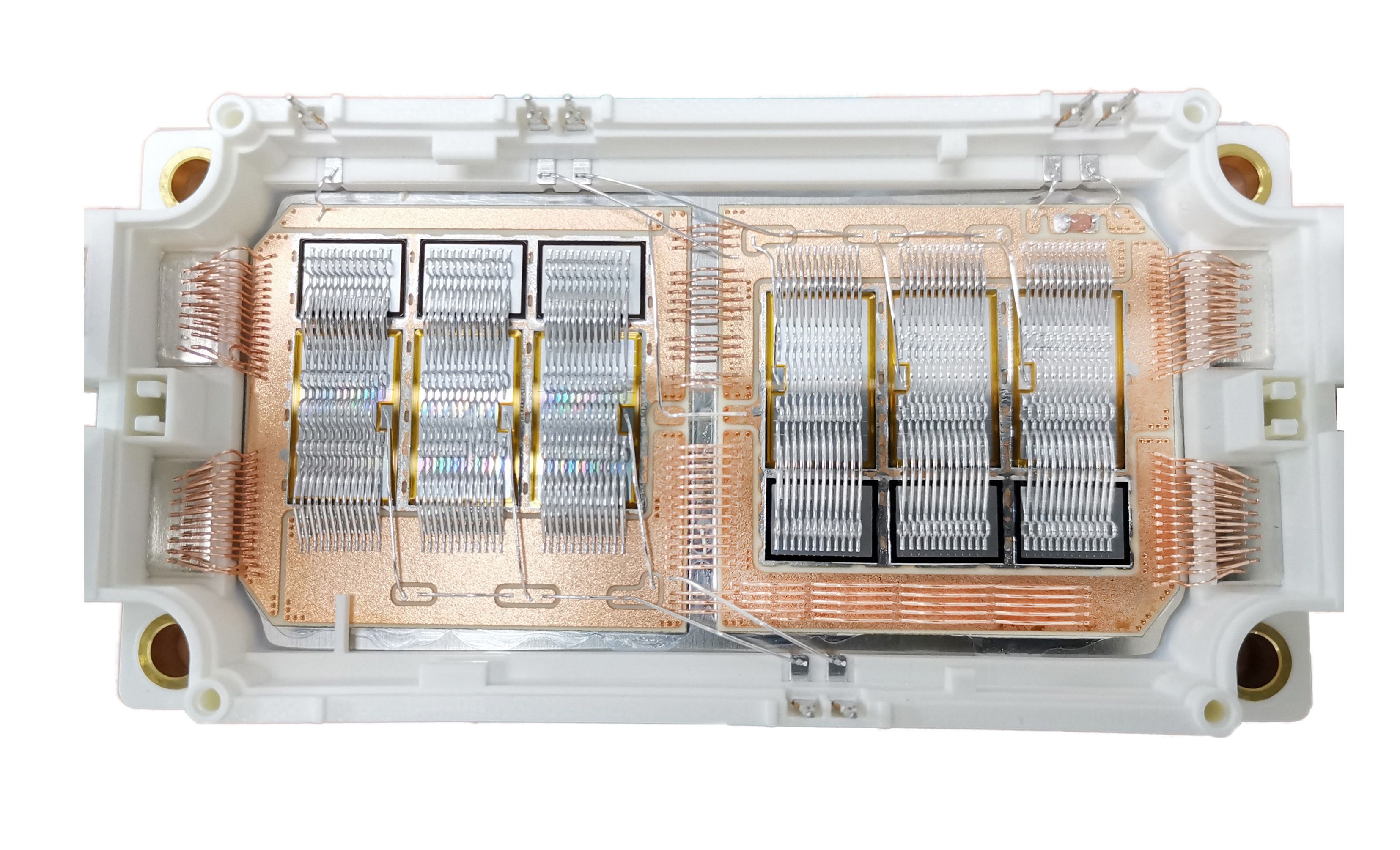
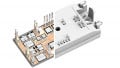
Figure 5. 1200 V, 900 A X 2 LoPak module
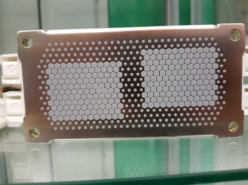
Figure 6. Module base plate with TIM
The “heart” of these new modules is the next generation of ultra-low loss, rugged Trench IGBT technology used to fabricate the silicon switch and optimized diodes. The IGBT devices have an aggressive fine gate pitch cell with novel termination and a degradation-free technology developed by Hitachi ABB Power Grids. This allows the device to switch higher current densities using an optimized operation point, with ideal characteristics for alternative power (wind and PV) and industrial (motor driver) applications.
Using the existing LoPak module design enables additional transient over-current capability by taking advantage of the IGBT module’s maximum operating junction temperature of 175 °C, compared to the typical 150 °C. The new 1200 V product is configured as a 900 A phase-leg (half-bridge) IGBT module, providing outstanding safe operating area (SOA) and over-temperature capability. Within its class, LoPak uniquely benefits from the know-how in robust electrical performance and high reliability.
Careful design and virtual prototyping ensured the LoPak module’s current distribution is well-balanced during switching and is well controlled under overload conditions. Additional analysis was undertaken to understand the impact of the higher total current for the 1200 V, 900 A x 2 product housed in the LoPak package with respect to materials and parasitics. The existing LoPak1 housing already included the use of a copper (Cu) base plate, press-fit connectors for the control terminals, and the option to have a pre-applied Thermal Interface Material (TIM) on the base plate to improve the thermal conductivity (Rth) of the module.
The analysis led to the redesign of the Cu pattern on the DBC substrate to place the chips in the best locations to minimize the temperature interactions, the stray inductance, capacitance, and resistance of the package, and optimize the current sharing between the IGBT/ diode pairs.
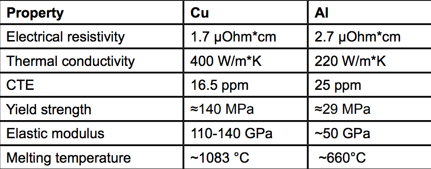
Figure 7. Properties of Cu and Al
Other optimizations of the LoPak materials include changing the bond wire material to Cu for the DBC/DBC and DBC/power terminal, to take advantage of the Cu material properties to support the very high current levels. The number of wires has been increased and a coated Cu power terminal is now used to support the increased power rating (Figures 7 and 8). Other than these changes, the LoPak module form and function remain the same as before.
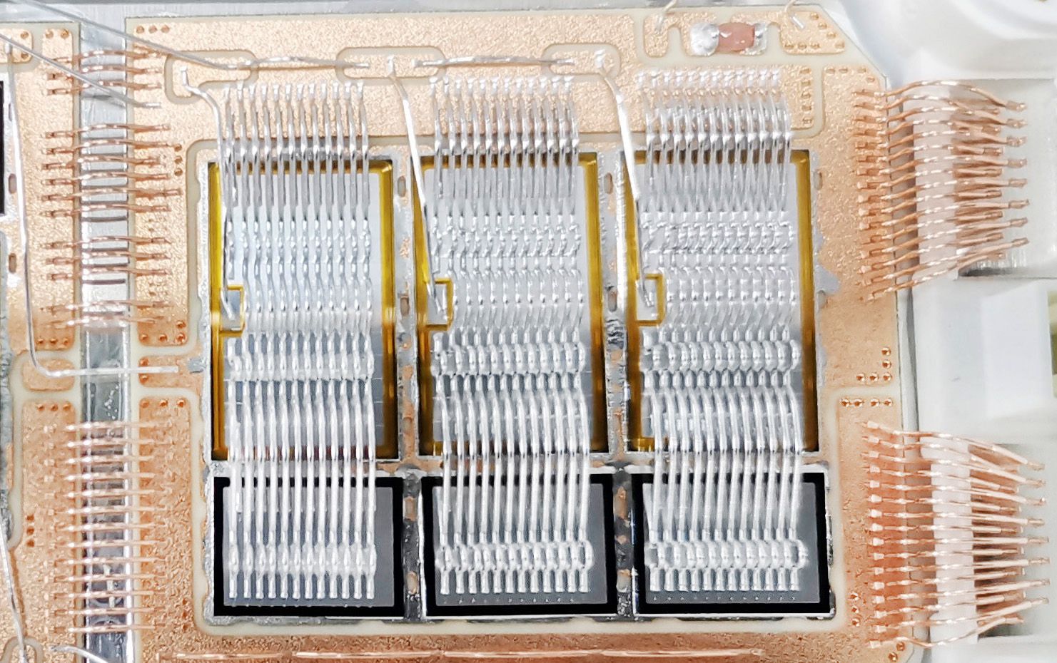
Figure 8. DBC/DBC, DBC/Power terminal wire bonding
The new 1200 V family of LoPak module products carry the same DNA for high reliability and robustness as the entire family of Hitachi ABB Power Grids’s high-power semiconductors.