 Facebook
 Google
 GitHub
 Linkedin
Power Modules for Combining Innovation, Flexibility and Power Capability in the Various 3-Level Topologies
This article introduces Mitsubishi Electric Corporation's new three-level topology power modules with optimized packaging for 3-level inverter designs.
Three-level topologies have demonstrated higher efficiencies, filter optimization potential and the capability of handling high DC-link voltages. To maximize the advantages offered by the 3-level topologies, Mitsubishi Electric offers new power modules which unlock the potential to realize innovative solutions for different power segments.
Power conversion applications have always had to deliver high performance while maintaining the required quality of power. The harmonic profile of the output power can be improved by increasing the switching frequency. However, an increase in switching frequency compromises the inverter efficiency. Historically, the conventional 2-level inverters have served the industry with its seemingly uncomplicated topology where developers have always had to strike a balance between efficiency and filter optimization. With the invention of the 3-level topologies, many new avenues are now open for improving the output harmonic profile without compromising on the system efficiency. With the option of being able to apply the ‘zero’ level, this topology brings with it the following inherent benefits:
- Efficiency and output power capability [1]: The superior switching loss profile of a 3-level inverter ensures that better efficiencies can be achieved. Thus, for the same dc-link, a 3-level based inverter can deliver a higher output power compared to the corresponding 2-level inverter.
- AC filtering [5]: For the same switching frequency, the 3-level topology utilizes the availability of the ‘zero’ level to deliver an AC output of higher power quality than the corresponding 2-level inverter. This naturally allows a significant reduction of the output filter inductance.
- dv/dt Filter [5]: Since the phase to neutral output of a 3-level inverter shifts between 0V and (+/- Vdc)/2 (unlike the 2-level output), the corresponding dv/dt across the load is naturally reduced by about 50%.
- Common mode voltage reduction [5][6]: In comparison with 2-level, significant reduction (about 25%) of common-mode voltage is possible in the 3-level topology.
While every segment of the inverter industry can avail the benefits associated with the 3-level topologies, grid-connected inverters (Solar, Wind, HVDC), UPS and medium-to-high power drives stand to benefit significantly by employing this innovative approach[3] [4].
Power Modules from Mitsubishi Electric for 3-level NPC inverters
The CM400ST-24S1 module has already been introduced and presented in good detail ([2] Bodos article Feb’2015). A new series of power modules with innovative packaging optimized for 3-level applications has been developed. The comprehensive line-up is shown in Figure 1. The CM500C2Y-24S is provided as a dedicated neutral clamp switch for efficiently realizing the T type 3-level topology.
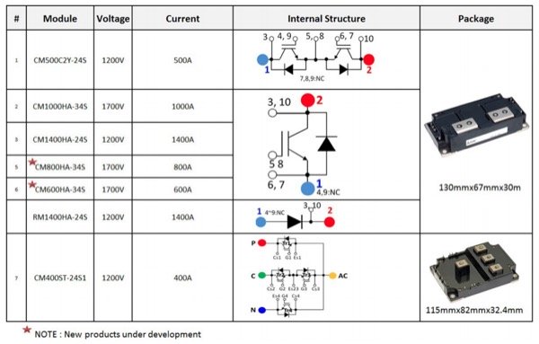
Figure 1: Line-up of the products dedicated for 3-level solutions
These power modules from Mitsubishi Electric are optimized for 3-level topologies with regards to the following parameters:
- Compact package size: For realizing an I type topology, in comparison with its counterparts from other manufacturers, the 1 in 1 modules (each 130 mm x 67 mm x 30 mm in size) offer about 20% reduction in mounting area. This was achieved by taking advantage of the superior thermal behavior of the Aluminium nitride (AlN) substrate and combining it with the CSTBTTM chip technology.
- Reduced internal inductance: The 1 in 1 modules have an internal inductance of only 8 nH. Internal stray inductance plays an important role in 3-level topologies as several elements are connected in series, unlike the traditional 2-level topologies.
- Reduced overall inductance: The combination of a low internal inductance, a reduced mounting area and the location of terminals for easy connections ensure a reduced overall inductance for the set-up.
- Access to auxiliary terminals: The module provides access to the auxiliary terminals on two sides for connecting the gate driver (without having the need to disturb the bus bar arrangement).
An example of how low inductance I-type and T-type 3-level topology bus bar designs can be realized is represented in Figure 2. As shown in this example, it is obvious that these modules are specifically optimized for 3-level topologies, thereby addressing the challenges associated with DC bus bar inductance, power density and flexibility.
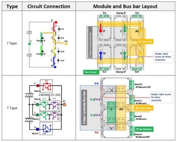
Figure 2: Sample 3-level constructions which can be realized for using Mitsubishi Electric power modules
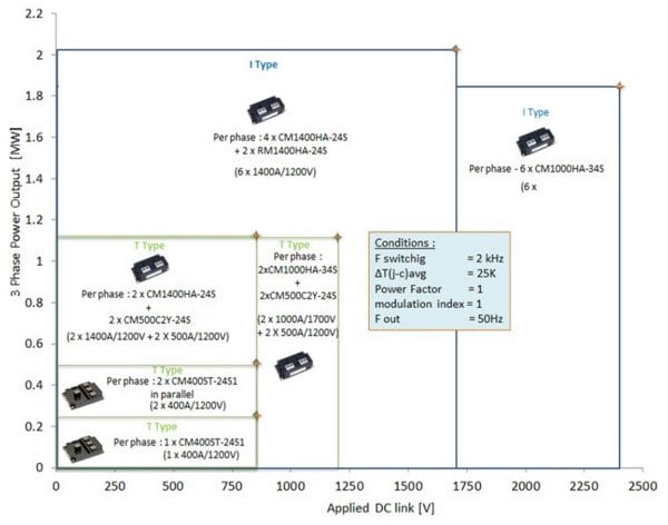
Figure 3: Power capability matrix for different 3-level solutions
Figure 3 shows the different power levels achievable by developing various 3-level topologies employing power modules from Mitsubishi Electric. The power levels are based on a conservative dimensioning of junction-case temperature rise of 25K considering a switching frequency of 2 kHz. Depending on the cooling system and the switching frequency, the output can obviously be further maximized.
Power levels
- 125 kW to 500 kW range: For a DC link voltage of 850 V, the CM400ST-24S1 with its inbuilt T type topology can deliver up to 250 kW in stand-alone mode. When used in parallel, about 500 kW output can be delivered.
- 500 kW to 2 MW range: When a DC link voltage of 1200V is utilized, two CM1000HA-34S (1000A/1700V) together with two CM500C2Y-24S (500A /1200V) in parallel can be employed to achieve more than 1 MW output. On the other hand, when an 850V DC link is considered, two CM1400HA-24S (1400A/1200V) can be employed together with two CM500C2Y in parallel to achieve more than 1 MW output power. With a DC link of 2400V, six CM1000HA-34S can be employed to develop a 1.8 MW inverter. Remarkably, utilizing a 1700V DC link, more than 2 MW output can be achieved by employing four CM1400HA-24S modules along with two RM1400HA-24S (neutral clamp diodes).
- Extended Megawatt range: It is obvious that by paralleling the options provided above, extended megawatt range inverters can be realized. An alternative solution for this class is to employ multi-level topologies.
As a result of these new products being available, the designer can choose the best fitting solution considering the power and DC voltage requirements. The designer is thus able to evaluate and accordingly select a suitable system voltage to achieve significant system-level benefits and thereby maximize overall efficiency
Employing the appropriate solution Figure 4 shows that for an inverter with 1200V dc-link voltage, the maximum output current achievable for different switching frequencies for a maximum allowable ∆T(j-c) avg = 25K (imposed on the first element in any module to reach this limit) depends on the topology employed. The T type topology has advantages with respect to a lower part count and the corresponding volume reduction. However, the equivalent I type topology brings forth interesting system-level benefits. Considering a fixed switching frequency of 3 kHz, it can be seen that the I type inverter is capable of delivering 1.41 times more current than the equivalent T type topology. Such benefit in power capability can also be used to allow an increase in the switching frequency (a factor of 2.66 for the 800A range) bringing significant benefits in passive component reduction. Depending on the weightage allocated to passives dimensioning and device count, an appropriate decision can be made.

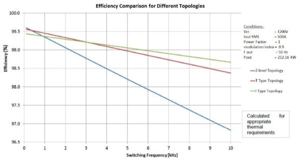
Figure 4: Analysis and comparison of performance using 3-level and 2-level topologies
Conclusion
While each module is designed to deliver the best electrical performance, the module packaging itself and the layout as well is optimized for 3-level inverter design. Combining these aspects with the variety of combinations possible using these different modules, designers now are allowed greater flexibility in realizing solutions which cater to their specific needs. To sum things up - it is clear, that there is flexibility in mechanical layout and flexibility in system level design parameters (choice of DC-link, filter). By addressing the specific needs of individual applications, it is obvious that solutions based on Mitsubishi Electric 3-level modules help achieve the maximum possible overall efficiency along with the best possible performance.
About the Authors
Narender Lakshmanan works as an Application Engineer at Mitsubishi Electric Europe B.V, Ratingen, Germany. He is responsible for power semiconductor-based power converter solutions and has past roles which include project management of EPC projects. He earned his Bachelor's Degree in Electrical Engineer at Anna University, Chennai, Tamil Nadu, India. He then acquired his Master's degree in Electrical Power Engineering at RWTH Aachen University, Aachen, Germany.
Thomas Radke is a Senior Application Engineer at Mitsubishi Electric Europe B.V, a company branch of Mitsubishi Corporation that focuses on electronics and electrical equipment manufacturing located in Ratingen, Germany. He earned his Bachelor's degree in Electrical Engineering and Electronics at Fachhochschule Düsseldorf (University of Applied Sciences - Dusseldorf). He also acquired his diploma in Associate Engineer in Automation Technology at Siemens Technology Academy - Düsseldorf.
Satoshi Kawabata works at Mitsubishi Electric Corporation, a Japanese multinational electronics and electrical equipment manufacturing company headquartered in Tokyo, Japan. It is one of the core companies of Mitsubishi. Power device works are specialized and concentrated at the Fukuoka Branch of the Corporation.
References
- MELCOSIM: IGBT thermal and loss simulation software, available at www.mitsubishielectric.com/semiconductors/ simulator/
- Marco Honsberg and Thomas Radke : “4in1 400A/1200V Module with T-type Topology for 3-Level Applications” Bodos Power Feb’2015, pages 26-28.
- Marco Honsberg, Thomas Radke : “3-level IGBT modules with Trench Gate IGBT and their thermal analysis in UPS, PFC and PV operation modes” - EPE 2009 – Barcelona - ISBN: 9789075815009
- Marco Honsberg and Thomas Radke: “A family of 3-level IGBT modules from 10A to 600A equipped with Trench Gate IGBT and their thermal performance under typical conditions for UPS and PV inverter operation” PCIM 2009 ISBN: 978-3-8007-3158-9
- L. Caballero, S. Ratés, O. Caubet, S. Busquets-Monge: Advantages of ac-ac power converters based on ANPC topology for wind applications”
- International Journal of Conceptions on Electrical & Electronics Engineering Vol. 1, Issue. 2, December 2013; ISSN: 2345 – 9603 : “Reduction of common mode voltage in three level neutral point diode clamped multilevel inverter using space vector pulse width modulation”
- Application note : 3-level application using 1 in 1, 2 in 1 and the 4 in 1 modules
This article originally appeared in the Bodo’s Power Systems magazine.


