Facebook
 Google
 GitHub
 Linkedin
Potential Transformer Operation, Applications and Accuracy
Learn about the operation and accuracy of potential transformers.
The high voltages typically seen on power lines are a hazard to technicians working on or near the power lines. It is a difficult task to design a voltmeter to measure these high voltages. A potential transformer is primarily a precision two-winding transformer that is used to step down high voltage to enable safe voltage measurement.
Operations
The stepped-down voltage from a potential transformer can be measured directly with a voltmeter. The line voltage can be calculated by multiplying the measured voltage by the turns ratio of the transformer. However, a better solution is to use a modified voltmeter.
The display of the meter can be modified with a new meter face or programmed to show a value corresponding to the actual line voltage, even though a stepped-down value was actually measured. The meter can multiply the measured value by the turns ratio to display the actual line voltage.
The primary side of the potential transformer is connected across the power lines (See Figure 1). Fuses can be added for safety and to make it easy to remove the potential transformer from the circuit for maintenance. To ensure that the voltage measurement is as precise as possible, the load on the potential transformer must be kept to a minimum. The voltmeter should be a high-impedance model to draw as little current as possible from the transformer. This non-changing load keeps the voltage ratio constant, and as the primary voltage changes, the secondary voltage changes proportionally.
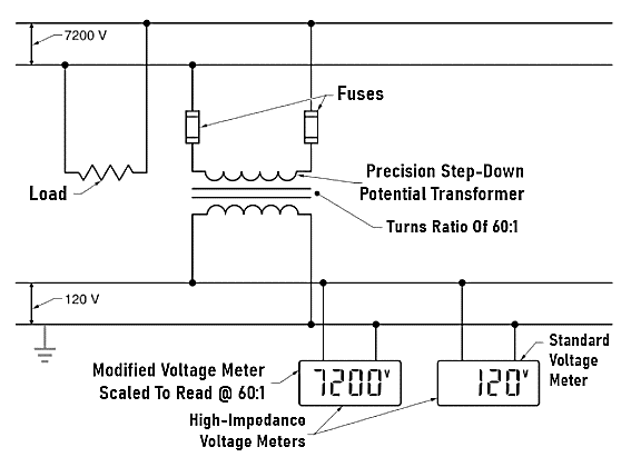
Figure 1. A potential transformer is used to step down the high voltage of a power line in order to make it easier to measure.
Potential transformers can be designed with almost any turns ratio so that the voltage can always be reduced to 120V. This allows standard voltage meters to be used. For example, a potential transformer with a turns ratio of 60:1 can be used to measure 7200V. The same meter can be used to measure 34.5kV if a potential transformer with a turns ratio of 287.5:1 is used to step down the line voltage to 120V. In this case, a different multiplication factor is used in the display or a different face installed on the meter.
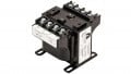
Potential transformers are usually fairly small. They are typically rated at 500 VA or less. Most of the size of a potential transformer is the heavy insulation on the primary winding required to withstand the high voltages present on power lines.
Accuracy of Potential Transformers
Potential transformers are often used for metering and billing. Therefore, the accuracy of potential transformers is critical. ANSI has established standard methods of classifying potential transformers for accuracy and load. The accuracy classification includes the standard load as well as the maximum percent error allowed.
The design, construction, and installation of the transformer all affect the accuracy. The load rating must include the total of all loads, including the circuit wiring connected to the secondary of the transformer. The total load must be calculated and the proper transformer selected from a table provided by the manufacturer.
A transformer correction factor is a number provided by the manufacturer that is used as a multiplier to correct for inaccuracies. The correction factor corrects for the effects of magnetizing current or internal phase angle shift created by the internal inductance of the transformer.
The transformer correction factor is used to define an accuracy class. Typical values of the accuracy class are 0.3, 0.6, and 1.2. A lower accuracy class number means a more accurate potential transformer.
Applications
Potential transformers have several common uses. Important uses for potential transformers are as voltage meters, to feed voltage relays, and for load shedding during peak load periods.
Voltage Relays
Potential transformers are often used as part of a system to monitor voltage on power lines. A sudden fall or rise in the voltage activates an under-voltage or an overvoltage relay. An under-voltage relay is switched when the voltage drops below a setpoint. An overvoltage relay is switched when the voltage rises above a set point. Under- and over voltage relays are used to protect equipment from under-voltage or overvoltage conditions. For example, a relay can signal a tap changer to step up or step down, or an under-voltage relay can start the transfer of a load from one supply to another in the event of a power failure (see Figure 2).
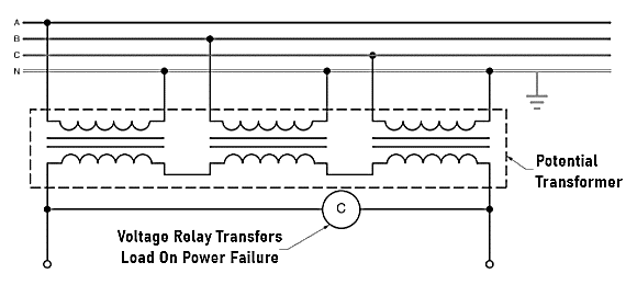
Figure 2. A potential transformer can be used to feed a voltage relay that is used to transfer a load in the event of a power failure.
Load Shedding
Voltage relays are also used in load-shedding applications. A potential transformer can be used to monitor a power line. When a power line is overloaded, and the voltage drops below a setpoint, the relay switches and removes some of the load from the power line. For example, a large industrial facility with its own generating equipment may be designed to automatically remove loads when the generating system is overloaded. The loads to be shed are specified in advance.