 Facebook
 Google
 GitHub
 Linkedin
“PFC + Inverter” Intelligent Power Module in 21mm x 36mm for Low Power Drives
This article discusses the features and advantages of intelligent power modules in terms of costs, size, thermal and overcurrent protection.
A PFC+Inverter IPM (Intelligent Power Module) optimized for low power Drives is introduced. A three-phase inverter and a single boost PFC stage are integrated in one single miniaturized DIL (Dual-In-Line) transfer molded type package with an SOI (Silicon On Insulator) gate driver. With this IPM, the size and cost of the system can be dramatically reduced
Overview The internal circuit of the new IPM is composed of inverter stage and PFC stage. The three-phase inverter stage has six 600V rated TRENCHSTOPTM IGBTs and six Emitter Controlled Diodes together with one SOI gate driver IC which provides integrated bootstrap circuit, and thermistor for temperature monitoring. The PFC stage consists of a 650V rated TRENCHSTOPTM IGBT and a Rapid Switching Emitter Controlled Diode which has fast and soft switching characteristics (figure 1).

Figure 1: Internal circuit
Cost reduction
Minimizing total cost is the most important consideration for system engineers when developing new motor drives. Not only material costs like IPM itself, heatsink and PCB but also development time to market are main factors of the total cost.
Miniaturized transfer molded package (package size and structure)
Package outlines of the IPM with high-level integration are shown in figure 2. The IPM builds in a compact size of Infineon Technologies CIPOSTM (Control Integrated Power System) Mini package of 21mm x 36mm x 3.1mm. The new IPM is UL approved (UL 1557 File E314539) and RoHS compliant.
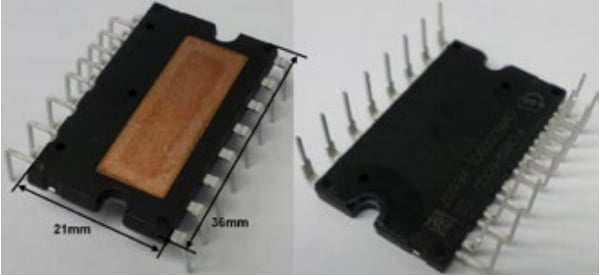
Figure 2: External view
DCB (Direct Copper Bond) which is a substrate with good thermal conductivity is adopted as a substrate for high thermal performance. Figure 3 shows the cross-section view of the new IPM. All of the major heat sources like IGBTs and Diodes are mounted on DCB, in order to fully utilize the heat transfer capability of this package. Therefore the new IPM can be an excellent solution for up to 3kW motor drives even though the package size is extremely compact [1].
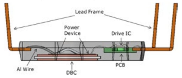
Figure 3: Cross-section view
Heatsink and PCB size
All of the power semiconductor components (i.e. a bridge rectifier, a discrete IGBT for PFC, a discrete boost diode, and an IPM for motor drive) are normally mounted on one heatsink for their heat dispassion. Figure 4 shows how much the size of PCB and heatsink can be reduced and the assembly process can be simplified by integrating discrete power semiconductors and drivers into one package [2].
Discrete PFC and inverter IPM solution The new IPM solution
The new IPM solution
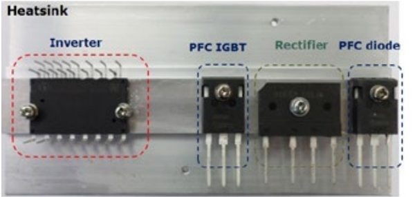
4a: Discrete PFC and inverter IPM solution
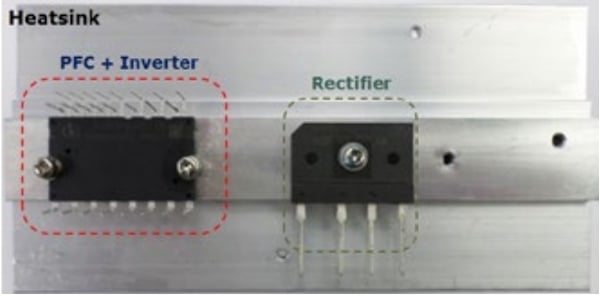
4b: The new IPM solution
Development speed up
Circuit design, artwork and PCB assembly take much time in the system development process (reference board, Figures 5 and 6). To reduce the time spent in the process, and quickly determine whether the new IPM can run a motor, a reference board has been developed. The minimum set of peripherals to operate a motor are mounted on the board and the others like PWM signals, +5/+15V dc power source, PFC inductor, DC-link electrolytic capacitor can be utilized from outside of the board via wire connection to the reference board.
650V rated PFC stage
Infineon Technologies has developed two kinds of products according to their PFC IGBT characteristics. They are High Speed 3 (HS3) for 20kHz switching frequency and TRENCHSTOPTM 5 (TS5) for 40kHz switching frequency, as listed in Table 1. The Rapid Emitter controlled Diode of Infineon is optimized to operate with TRENCHSTOPTM IGBT as a boost diode in PFC topology. It combines low VF for lower conduction losses and low Irr to reduce Eon of the IGBT [3]. All of the power devices have 650V of voltage rating and it provides higher reliability and ruggedness against unstable AC grid [4].
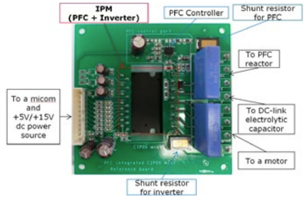
Figure 5a: Reference board structure Frontside

Figure 5b: Reference board structure Backside
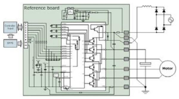
Figure 6: Application example of the reference board
Features of inverter stage
The inverter stage has many functions for the safe operating of Inverter. These functions can be achieved by a rugged SOI gate driver and a thermistor.
- Allowable negative VS potential up to -11V for signal transmission at VBS=15V
- Integrated bootstrap functionality
- Under-voltage lockout at all channels
- Cross-conduction prevention
- All of 6 switches turn off during protection
- Overcurrent shutdown
- Temperature monitor
Overcurrent protection
The new IPM monitors the voltage of ITRIP pin and when the voltage exceeds the VIT, TH+ (positive going threshold voltage), a fault signal is activated and all the 6 IGBTs are turned off. The maximum overcurrent trip level is generally set to below 2 times of the nominal rated collector current [5].
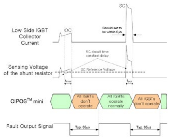
Figure 7: Time chart of overcurrent protection
Over temperature protection
For over temperature protection, a thermistor is integrated in this IPM. The resistance is typically 85kΩ at 25°C and 5.4kΩ at 100°C (Figure 8).

Figure 8: Thermistor resistance vs. temperature
As shown in Figure 9, the VFO pin is connected directly to ADC and fault detection terminals of the microcontroller because the thermistor is connected in parallel with fault out terminal which has open-drain configuration. For example, when pull-up resistor R1 is 3.6kΩ VFO voltage at about 100°C is 2.95Vtyp. at Vcrt=5V and 1.95V at Vcrt=3.3V as shown in Figure 10.
Thermal evaluation
Figure 11 is the test circuit and measured waveforms which show the test system’s operating status for evaluating thermal performance at input power of 2kW. The operating conditions are PFC controller=ICE2PCS05G, input power PIN=2kW, AC input voltage VIN=220V/60Hz, DC-link voltage VDC=400V, switching frequency of inverter=5kHz, switching frequency of PFC=20kHz, R-L load (R = 13.75Ω, L = 2.96mH, Power factor=0.99), MI=0.69, Gate resistor Rg=5.1Ω, ambient temperature Ta=25°C. The device under test is IFCM15S60GD. The input power factor is about 0.995 and THD is about 9.78%.
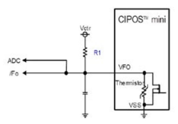
Figure 9: Circuit for over temperature protection
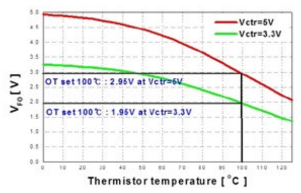
Figure 10: VFO voltage vs. temperature

Figure 11a: Test circuit and waveform of the new IPM, Test circuit

Figure 11b: Test circuit and waveform of the new IPM, waveform
The case temperature under PFC IGBT’s position is about 67.5°C as the highest point and it is higher than that of the inverter part. IFCM15S60GD is enough to deal with over 2kW power.
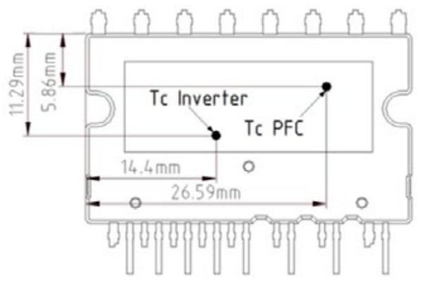
Figure 12a: Temperature measurement point and test results of the new IPM (IFCM15S60GD), Temperature measurement point
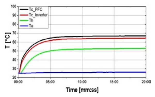
Figure 12b: Temperature measurement point and test results of the new IPM (IFCM15S60GD), temperature graph
Summary
New Intelligent Power Module is the best solution with inverter and PFC topologies for variable speed motor drive such as room air conditioner. Infineon Technologies owns all necessary technologies and is committed to support its customers to realize compact and more efficient solutions with minimized system size, total cost and time to market.
About the Authors
Byoungho Choo, Hyosang Jang, Junbae Lee, Minsub Lee and Daewoong Chung all works at Infineon Technologies Power Semitech, Korea, a group subsidiary of Infineon Technologies based in South Korea, with the head office in Cheonan. It operates in the Semiconductor and Other Electronic Component Manufacturing industry. Infineon Technologies Power Semitech Co.,Ltd. was incorporated on October 14, 2009.
References
- S Park, J Cho, H Kwon, J Lee, D Chung: “A Compact Intelligent Power Module with High Thermal Performance for up to 4kW Power Motor Drives”, PCIM Europe 2014, Nuremberg, Germany.
- H.Jang, B.Choo, J.Lee, M.Lee, D.Chung: Infineon Technologies Power Semitech, “New high Level Integrated Intelligent Power Module with Three Phase Inverter and Power Factor Correction Topologies Optimized for Home Appliance”, pp863-870 PCIM Europe 2016, Nuremberg, Germany.
- “650V Rapid Diode for Industrial Applications”, Application note, Infineon Technologies AG V2.0, Jul. 2014
- S Shim, B Choo, J Lee, D Chung: “A New High Efficient 2-Phase and 3-Phase Interleaved Power Factor Correction Boost Converter typed Intelligent Power Module with high switching capability for low power home appliances”, ICPE 2015 Asia, Seoul, Korea.
- “CIPOSTM Mini Inverter IPM Technical Description”, Application note, Infineon Technologies
This article originally appeared in the Bodo’s Power Systems magazine.


