Facebook
 Google
 GitHub
 Linkedin
6 Techniques for Controlling Harmonic Distortion
Harmonics–currents or voltages at a multiple of the power systems’ fundamental frequencies– originate from non-linear loads in power systems. This article will introduce six techniques necessary to reduce harmonic distortion.
To catch up on this series, please follow this link:
Mitigating Harmonics in Power Systems
The earliest method of controlling problems associated with harmonics involved the use of a single-tuned filter which offered a lower impedance path for the harmonic currents. Interestingly, finding a harmonic-producing load in the range of megavolt-ampere in industries that operate without harmonic filters is not difficult. Large producers of harmonics in the industrial sector may still adopt traditional harmonic filtering methods to control the disturbances that arise beyond the system’s metering point that affect sensitive processes and equipment. These filtering methods are not cost-effective for residential and commercial facilities. This article looks at the techniques that can be used to control harmonics and reduce the distortion harmonics cause on the signal flowing in power systems.
1. Network Reconfiguration
Network reconfiguration is one of the measures that can help reduce harmonics. This process starts by identifying the users or sectors that produce a lot of harmonic current to the power system and categorizing them according to the characteristics of the frequency content.
Suppose the use of harmonic filters is not a consideration. In that case, mixing both linear and non-linear electric loads on the feeder can reduce harmonic distortion since linear load works as a natural attenuator controlling the parallel peaks of the resonant.
The top objectives of network reconfiguration include:
- Minimizing network power loss
- Minimizing network voltage sag during switching or faulting
- Minimizing node voltage harmonic distortion
- Minimizing system unbalance
The branch exchange technique is employed during network reconfiguration. This is a design technique where an unenergized tie branch is introduced in the power network. This is demonstrated in Figure 1 below.
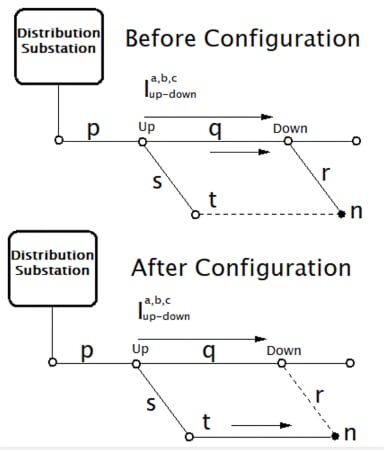
Figure 1. Before and after configuration diagram. Image used courtesy of Simon Mugo
Power to node n was flowing through path pqr previously and after configuration, the power path changes to path pst. the advantage of this technique is the automatic maintenance of the radial configuration and no calculations are required to fulfill the purpose.
2. Increase Supply Mode Stiffness
Increasing the ratio between the present short-circuit and the rated load currents mean a more substantial electric supply node. This is common when power suppliers increase the size of their power substations. It also happens when large power consumers like industrial clients add other supportive cogeneration on the main supply bus to improve the peak demand during operations.
The ratio between the short circuit and the load current gives us the source stiffness of the power system. A stiff AC supply increases the chances of short-circuit current being available.
With a strong supply node, be assured that you have a better chance of absorbing transient disturbances present in the network and help attenuate the effects of the large inrush currents of the transformer, cable energizing, and large motor loads starting.
With high short-circuit currents, expect low impedance sources, which in turn form an inverse function of the size of the transformer. We can illustrate this by computing the impedance change when an old worn-out transformer-rated MVA1 is substituted with a new transformer-rated MVA2.
By using the transformer impedance fundamental expression
\[X_{TRANSF}=\frac{kV^{2}X_{leakage}}{100MVA}\]
We end up with
\[=\frac{\frac{kV^{2}_{2}X_{leakage2}}{100MVA_{2}}}{\frac{kV^{2}_{1}X_{leakage1}}{100MVA_{1}}}\]
Assuming that all the parameters in the equation are the same reduces the equation above to:
\[\frac{X_{MVA2}}{X_{MVA1}}=\frac{\frac{1}{MVA_{2}}}{\frac{1}{MVA_{1}}}=\frac{MVA_{1}}{MVA_{2}}\]
This equation gives us the impedance ratio for how the new transformer to the old transformer varies. For example, a 60-MVA transformer will give an impedance twice as smaller as a transformer of 30-MVA will give and increase the short-circuit by double, where the assumption is that the two transformers suffer the same leakage current problem.
At the harmonic frequency, capacitive and inductive impedances of the power system vary according to the frequency function.
For the inductive load
\[X_{Lh}=h\omega_{L}\]
For the capacitive load
\[X_{Ch}=\frac{1}{h\omega C}\]
Inductive components of the power system are primarily affected by a stiffer power source. Harmonic currents generate a voltage drop that is affected by the system’s inductive reactance, which is made of the feeder and the components of the substation.
For short feeders, the dominant component is the source impedance. In such situations, expect harmonic currents to reach the system’s substation creating harmonic distortion. With stiffer systems, expect smaller harmonic distortion.
3. Adding Multi-pulse Converters for Harmonic Cancellation
Here, we can employ half-wave and full-wave rectifiers. For half-wave rectification, it produces the DC output that saturates a transformer, and this can be limited by the use of full-wave rectification.
Six-pulse unit is the most basic available polyphase converter. 12-pulse unit is used to eliminate harmonics of a lower order that is 5th and 7th.
Figure 2 below is a pulse converter connection.
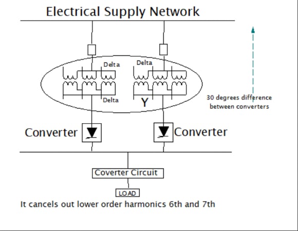
Figure 2. Pulse converter connections. Image used courtesy of Simon Mugo
If you want to reduce other harmonic currents, you carry out a phase multiplication. For example, a 24-pulse unit is constructed from a combination of four-six pulse full-wave rectifier bridges, each having a 15 degrees phase shift as compared to other rectifying units. This is made possible by utilizing phase-shifting transformers that separate the additional windings that are connected in a zig-zag. See Figure 3 below.
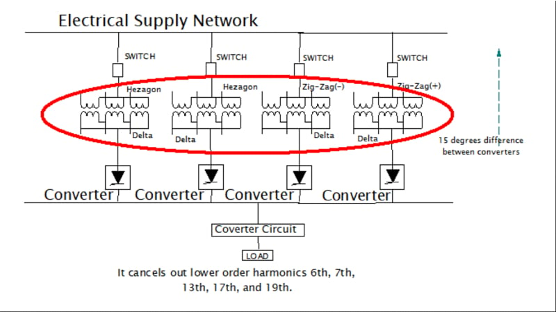
Figure 3. Pulse converter connection. Image used courtesy of Simon Mugo
See the following conditions for harmonic elimination using a six-pulse rectifier:
- Transformers used in the connection have the same leakage impedances and transformation ratio.
- The load is divided into equal parts among the available converters
- All converters have similar firing angles
- The difference in phase between transformers is 60/N degrees, where N is the number of sections.
The equation for the characteristic harmonic reduction can be written as
\[h=kq\pm1\]
where
h is the systems harmonic order, N is the available number of the six-pulses rectifier, q is 6×N and K is an integer given by 1,2,3,…..,n
4. Series Reactors
In industries, series reactors have been incorporated into the control of short circuits for a long time. They are used in smelting industries, power substations, and steel plants. Sometimes in industries, the series reactors are perfectly used in attenuating harmonics.
The current waveforms that are nonlinear have harmonic distortion. Introducing line reactors limits the number of inrush currents moving into the drive rectifiers. This reduces the peak current, rounds off the waveform, and minimizes the harmonic distortion. the distortion of the current is reduced to approximately 30%. If the current distortion is severe, it also distorts the system powering voltage. If the system drains too much harmonic current, it causes a flat topping on the waveform of the voltage. Introducing a reactor is a way of controlling the composition of the current, and this way, the harmonic distortion occurring on the voltage is reduced. See Figure 4 below.
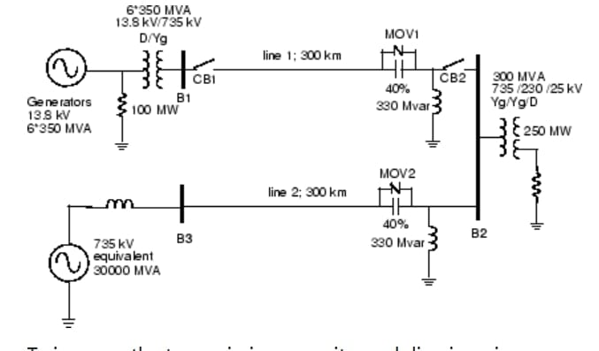
Figure 4. Series and shunt compensated transmission system. Image used courtesy of MathWorks
5. Phase Balancing
Variations in the single-phase electric loads can lead to an imbalance of current in the three-phase conductors, creating a dissimilar drop in the voltage, which induces an unbalanced phase-to-phase voltage.
This unbalanced phase-to-phase voltage is hazardous to the distribution feeder, especially when there are poor measures for compensation of the stray voltage. A perfectly balanced system is hard to attain but always try as best to balance the phases, which reduce harmonics.
Phase Voltage Unbalance
To determine the unbalance voltage most efficiently, you need to know how to calculate it.
Start by calculating the deviation using the formula below:
\[Voltage\,unbalanced\,in\,Percentage=\frac{Maximum\,deviation\,from\,the\,average\,voltage}{Average\,voltage}\times100\]
If the system operates under an unbalanced phase, the following will happen:
- Overheating of the cables due to unbalanced line currents.
- Unprotection of the MCB, MCCB, fuses, etc.
- Faults in the underground cables.
Phase balancing leads to uniform distribution of the load across the three-phase power lines of the system. If the system is unbalanced, there will be wrong utilization of the feeder capacitor for the system's future load demand. With good current balancing, there will be the eradication of the extra current stress on the overloaded line or phase and placed on the underloaded line or phase, thus creating room for future demand. The phase balancing also improves the system's feeder capacity and voltage quality and reduces losses. See Figure 5 below, a diagram for a basic balanced three-phase power.
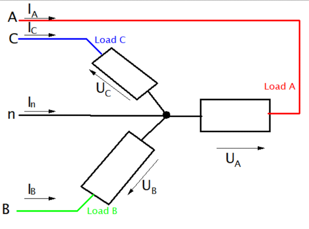
Figure 5. Basic balanced 3-phase power. Image used courtesy of Simon Mugo
6. Load Grouping
Too many electric networks may come with nonlinear loads that contain different spectral content. Grouping these loads to classes made of a similar harmonic spectrum helps optimize the location, installation, sizing, and selection of the harmonic filters.
Several electricals can exist in a circuit network resistive loads, inductive loads, and capacitive loads, all having different levels of harmonics introduction into the power systems. All these loads find use in various sectors. In domestic or residential loads, modest power is consumed. Commercial, industrial, and municipal loads are other areas where electricity is utilized. All these areas consume power of different harmonics and can be classified to help reduce how harmonic from one sector is spread to the other.
We have different loads consuming different types of voltages. Some consume 208 V, others 120 V, some 240 V, and so on, and these loads have to be grouped well. See the voltage consumption system in Figure 6 below, which has different power loading.
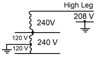
Figure 6. 120/240 V, 3-phase, 4-wire, open-delta system. Image used courtesy of Simon Mugo
Takeaways of Reducing Harmonics
The article has introduced the six techniques engineers can employ to minimize harmonics in power systems. They include:
- Network reconfiguration helps reduce harmonics, which is the process where the users that produce large harmonics are identified and categorized according to the type of harmonics they produce.
- An increase in supply mode stiffness means a more robust electric supply node which is the ratio between the short circuit and the load current. The stiffer the AC means a higher probability of short circuit availability.
- Adding multi-pulse converters for harmonics cancellation through the employment of half and full-wave converters helps eliminate harmonics. Here six-pulse is the most available polyphase converter.
- Series reactors minimize harmonics in smelting and steel plants.
- Phase balancing is another method suitable to minimize harmonics. Remember unbalanced phase is a source of harmonic.
- Load grouping is where similar loads are placed together. Nonlinear loads with different spectral content are available in electrical systems, and grouping these loads helps select and size harmonic filters.
Featured image used courtesy of Adobe Stock