Facebook
 Google
 GitHub
 Linkedin
Next-Gen PV Optimizers Use eGaN FET and Dedicated ASIC Controller
As the adoption of photovoltaic systems continues, pressure on manufacturers drives innovation and the adoption of new technologies to reduce cost without compromising reliability.
This article is published by EEPower as part of an exclusive digital content partnership with Bodo’s Power Systems.
There are two main configurations of low-power commercial and residential PV systems. The first configuration is the micro-inverter, which uses an inverter for each panel in the installation, ensuring each panel can deliver its full energy potential. The second is the string inverter, which connects multiple panels together and feeds into a central inverter. However, this setup suffers from poor energy harvesting when one or more panels are shaded.

Image used courtesy of Adobe Stock
Innovative augmentation has been introduced in the form of optimizers; power modules that optimize energy harvesting for each panel. These optimizers emerged to compete with the energy-harvesting capability of micro-inverters. The main disadvantage of micro-inverters has been their cost due to the need for an AC converter in each power module. Optimizers can improve the cost equation because their structure is significantly simpler, and they are compatible with existing string inverters.
This article presents an overview of how PV optimizers work and how converters can benefit from new technologies such as eGaN FETs. GaN FETs have demonstrated superior performance in many hard-switching applications. Their high reliability makes them ideal candidates for optimizers. Additionally, GaN FETs help shrink converter size, contributing to cost reduction.
String Inverter Energy Harvesting Overview
A common configuration for a photovoltaic system is the string inverter system, as shown in Figure 1. In this system, the DC outputs from several PV panels are wired together in series and fed into a central string inverter. The string inverter then converts this DC voltage to AC current, fed into the grid. The upper graph in Figure 1 shows the individual PV panel voltage-current power characteristics based on shading and equal solar insolation levels—less shading results in higher current. The red trace in the lower graph illustrates the available power from the PV string, with multiple peaks corresponding to the various current and voltage levels for each panel’s contribution. Connecting panels in series forces the same current through all, making it impossible to operate all of the panels at the maximum power point simultaneously, thus impossible to maximize energy harvesting. The green trace represents the total potential power the combined PV panels could produce if each operated at its maximum power point. The difference between the two graphs is substantial and shows the need for an optimizer to improve system-level energy harvesting capability.
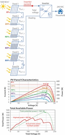
Figure 1. Overview diagram of a sting inverter-based solar system that shows the effect of shading on the output characteristics of each panel in the upper graph and the effect on total available power in the lower graph. Image used courtesy of Bodo’s Power Systems [PDF]
Optimizer Overview
An optimizer is a DC power converter inserted between the PV panel and the series string connection to the central string inverter. It has two main functions: 1) to track the maximum power point of the attached PV panel and 2) to deliver that power to the string connection as a constant power source. The most popular topology for an optimizer is the back-to-back buck-boost converter, as shown in Figure 2.
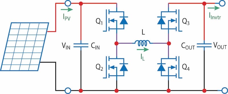
Figure 2. Power schematic of a back-to-back buck-boost converter, sourced by a PV panel, suitable for an optimizer. Image used courtesy of Bodo’s Power Systems [PDF]
The back-to-back buck-boost converter is popular because it can be configured to operate with high efficiency, particularly when the voltage conversion ratio is kept low.
The optimizer works by seeking the maximum power point of the panel and re-scaling the voltage and current to match the current drawn by the inverter. Figure 3 shows the optimizer’s output characteristics for the various power levels in Figure 1’s upper graph. The black dashed trace represents the current drawn by the inverter, which maintains its own maximum power point tracker (MPPT).
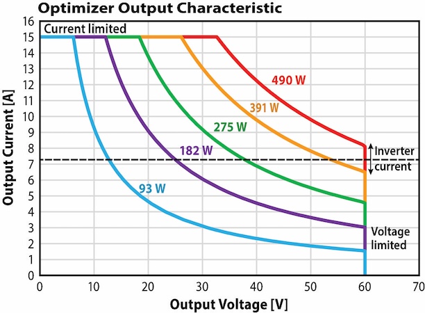
Figure 3. Optimizer output characteristics for various panel insolation levels. Image used courtesy of Bodo’s Power Systems [PDF]
There are three basic modes of operation for the optimizer: 1) constant current, 2) constant power, and 3) constant voltage. The constant power mode is the optimizer’s normal operating mode, while constant voltage and constant current modes are based on the converter’s limits, during which the optimizer no longer harvests the maximum available power from the panel. Constant current mode occurs when the string inverter attempts to draw more current than the optimizer circuit can deliver, while constant voltage mode occurs when the string inverter draws too little current. The system is optimized when the string inverter uses its MPPT algorithm to find the maximum power for the combined outputs of optimizers, following the green trace in Figure 1’s lower graph and when the dashed black trace of Figure 3 intersects all the panels' constant power traces.
Overview of the Demonstration Board
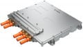
The EPC9178 is a versatile four-switch back-to-back converter capable of operating in buck and boost modes, and it can be configured to operate as a PV optimizer. Its input voltage range is 30 V to 60 V, with three selectable output voltage options: 30 V, 45 V, and 60 V. Both input and output currents are limited by the controller to 15 A, and the output current limit can be enabled or disabled by the user. EPC9178 operates at a fixed switching frequency of 450 kHz across all operating modes. This high frequency helps reduce the size of passive components, such as the inductor, and bus capacitors, resulting in a compact design, as illustrated in Figure 4. The converter’s small size and lightweight design facilitate installation and maintenance, contributing to industry-leading power density for solar applications. Despite its small size, the EPC9178 achieves a respectable peak efficiency of 98%.
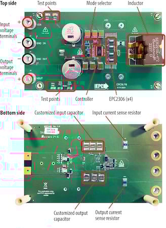
Figure 4. Functional circuit blocks of EPC9178 demonstration board. Image used courtesy of Bodo’s Power Systems [PDF]
The key to the EPC9178’s high efficiency and power density is its use of 100 V rated EPC2306 GaN transistors, which have a very low on-resistance of 3.8 mΩ. The EPC2306 is available in a 3 x 5 mm PQFN package and is built on proven reliable eGaN FET technology. Their low on-resistance minimizes conduction losses, while their low output capacitance (COSS) enables short switching times and reduced switching losses. This combination of low conduction and switching losses improves overall efficiency and simplifies thermal management compared to equivalent silicon MOSFETs.
The EPC9178 uses the LM5177 IC from Texas Instruments, which integrates the controller and the four gate drivers onto a single chip. This results in a simple, compact solution with a minimal component count.
Experimental Results
The EPC9178 was experimentally evaluated based on a typical PV panel voltage range. Three input voltages–30 V, 45 V, and 60 V–were evaluated, with the converter delivering a fixed output voltage of 30 V. Figure 5 shows the measured efficiency and power losses of the EPC9178, with a peak efficiency of 98%. For the 60 V input, thermal and current limits are applied.
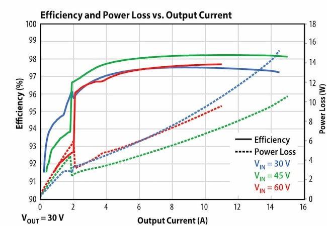
Figure 5. Shows the overall efficiency and power loss of the EPC9178 Board with various input voltages and delivering 30 V into the load as a function of load current. Image used courtesy of Bodo’s Power Systems [PDF]
Takeaways
The EPC9178, equipped with high-performance, 100 V rated low RDS(on) EPC2306 GaN FETs and the LM5177 controller from Texas Instruments, offers exceptional efficiency and a compact design. These attributes make it an ideal choice for applications demanding high efficiency, small size, and longevity–such as optimizers in photovoltaic systems, as demonstrated by the experimental unit. The LM5177 is part of the growing ecosystem specifically designed for GaN FETs. As renewable energy systems continue to evolve, innovative technologies like GaN FETs will be key to driving further improvements in cost, performance, and reliability across the industry.
This article originally appeared in Bodo’s Power Systems [PDF] magazine and is co-authored by Parinda Chantarasereekul, Xiaoping Jin, Alejandro Pozo, Mark Gurries, and Michael de Rooij of Efficient Power Conversion.