Facebook
 Google
 GitHub
 Linkedin
Overcurrent Protection, Grounding, and Applications for Control Transformers
Learn about how control transformers are used in overcurrent protection and grounding.
NEC® Section 430.72(C) lists requirements for transformers used in motor control circuits. This section says that control transformers with a current in the primary winding of less than 2A shall be protected by an overcurrent device of 500% or less of the rated primary current. Accessories such as fuse kits that mount on the unit and covers that isolate the front and terminal strips are readily available.
It is common industry practice to protect a control transformer on both the primary and secondary sides. The reason for fusing both sides of a control transformer is to protect the primary if there is a short in the secondary. For example, a heating element contactor controlled by a temperature switch is used to control a 3-phase heater (see Figure 1). The control circuit has a fuse between the control transformer and the switch. The power circuit has fuses between the source and the control transformer. If either circuit has an overload, a fuse will open the circuit.
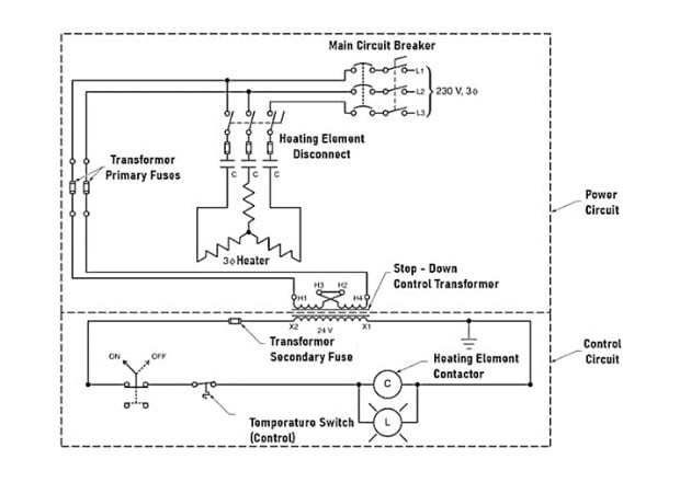
Figure 1. A control transformer is normally fused on the primary and secondary sides for maximum protection.
The phase difference between the primary and the secondary is 180°. This tells us that, as the current in the primary flows from H1 to H4 in the primary, the current in the secondary flows in the opposite direction from X1 to X2. As the current in the secondary increases, the flux increases. This flux has opposite polarity to the flux in the primary, and the fluxes cancel. This lowers the reactance and the current increases.
A short in the secondary results in a high current in the secondary. The high current increases the flux that opposes the flux induced in the primary. This results in a higher current in the primary. As the current increases in the primary, the reactance decreases, and the primary becomes more resistive than reactive.
The reduced reactance allows too much current to flow in the primary. This change in current happens very quickly, and a short in the secondary can induce enough current in the primary to cause damage. Therefore, both sides of a control transformer should be fused.
Grounding
A control transformer may have one side of the secondary grounded. A grounded system is a control system with a grounded secondary in the control transformer. When one side of the transformer is grounded, a voltmeter can easily be used to test the system. One lead of the voltmeter can be connected to the ground, and the other lead can be used to measure voltages in the control circuit.
A control transformer may have the secondary ungrounded. A floating system is a control system without a grounded secondary in the control transformer. When the secondary is not grounded, a voltmeter cannot be used to measure voltage to the ground to troubleshoot the control circuit. Voltages in the control circuit must be measured relative to one side of the control transformer (see Figure 2).
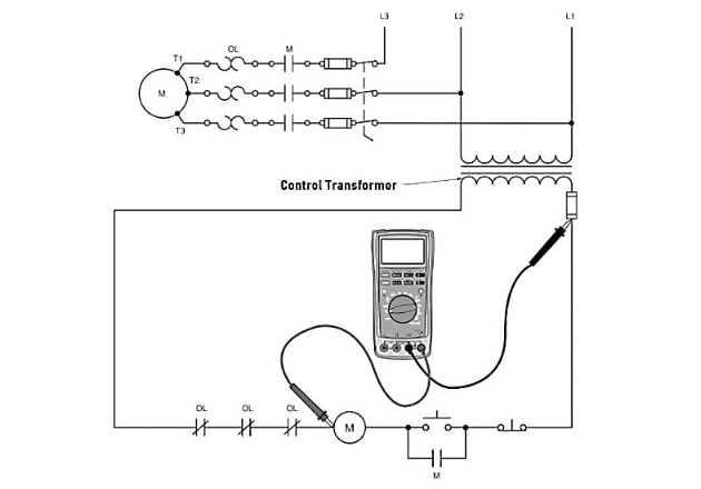
Figure 2. Voltages in a floating system must be measured relative to one side of the control transformer instead of to the ground.
Power supply isolation from the ground may be necessary to prevent ground loops. A ground loop is a circuit with more than one point connected to the earth ground, with a potential difference between the two ground points. The voltage difference can produce a circulating current in the ground system. Isolation transformers are used to prevent a ground loop from causing problems in a circuit (see Figure 3).
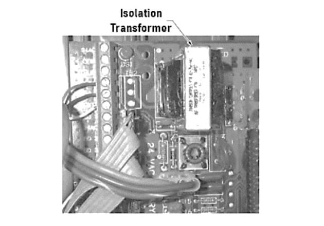
Figure 3. Isolation transformers can be used in controllers to prevent a ground loop from causing problems in the circuit.
Control transformers for HVAC systems are usually rated at 120V or 240V on the primary and 24V on the secondary (see Figure 4). This allows a low-voltage jacketed cable to be run from the control panel to the thermostat. Many commercial applications running HVAC units at 240V or 480V 3-phase systems use a dual-voltage control transformer with a 24V secondary.
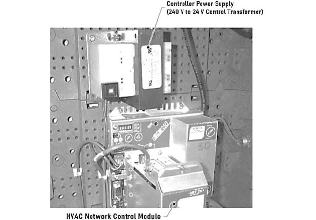
Figure 4. HVAC control systems often use control transformers to step down the 240 V supply to 24 V for the control circuit.
Applications
Most machines in the industry contain a transformer in the panel to provide power for logic inputs, relays and solenoids, panel lighting, and numerous other loads in industrial process control. When a disconnect is pulled to remove power at the control panel, the control power is also turned off.
Most control transformers used in control panels are the dual-voltage type. Common applications of control transformers are to provide power for HVAC control systems and to provide power to control a heating element.
Heating Element Control
A control transformer may be used to supply power to contactors for a heating element (see Figure 5). The control transformer provides low-voltage power to the contactors. A control device, such as a float switch, pressure switch, thermostat, or another device, closes a contact. This allows power to flow to the heaters. For safety reasons, heater controls are usually designed to be normally open and only operate when needed.

Figure 5. A heating element is controlled by contacts powered by the low-voltage supply from a control transformer
Bell Transformers
A bell transformer is a transformer used to supply low-voltage, low-power circuits, such as doorbells, annunciators, and similar systems. The primary application for bell transformers is as power supplies for doorbells and annunciators. Other common applications include thermostat circuits, music or intercom systems, burglar alarms, and hard-wired water sprinkler systems.
Bell transformers work in the same way as a standard step-down control transformer. They generally consist of an insulated panel with four screws for connection. One of these screws is common, while the other three are taps that allow different voltages to be taken from the coil. These taps are typically 6V, 12V, 16V, and sometimes 24V (see Figure 6). The primary voltage is typically 120V, but it could be 240V.
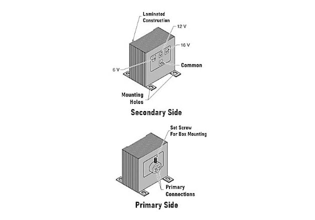
Figure 6. A bell transformer has taps for 6 V, 12 V, and 16 V to power low-power devices such as doorbells and annunciators.
Small bell transformers are usually rated for about 20 VA to 40 VA and can be mounted in a number of fashions. The primary side may have a threaded nipple that allows it to be attached to a box cover with a lock nut through a knockout. It may also have a tab with a set screw at the end that also fits through a knockout for mounting. These transformers also come equipped with mounting feet for control panel applications.