Facebook
 Google
 GitHub
 Linkedin
Modular Multi-Level Converter Technology for Medium Voltage Applications
This article introduces some of the technologies Amantys has developed to realise a full-power MMC converter for medium-voltage applications.
The development of MMC sub-modules for medium-voltage applications requires careful consideration and design trade-offs. Amantys shares some details about decisions made in development of a flexible and scalable architecture with some innovative features.
The modular multi-level converter (MMC) is widely studied and a topic of research in many universities and companies around the world at present. High-voltage dc transmission (HVDC) has used MMC technology for many years, and in the last decade voltage-source converter (VSC) HVDC systems based on IGBTs have been a viable alternative to the more mature line-commutated converter (LCC) HDVC system based on thyristor technology [1].

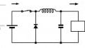
Figure 1: Three phase MMC schematic.
A typical MMC comprises many sub-modules (also known as cells) connected together into chain-links to form, together with arm inductors, the phase arms, see Figure 1. In an HVDC system, there are often many hundreds of sub-modules in a chain-link, which can support hundreds of kilovolts. Each sub-module is usually a half-bridge (as shown in Figure 1) or full-bridge (Figure 4) depending upon the system requirements. The half bridge sub-module is cheaper, containing two switches rather than four, but lacks the ability to block some fault currents. On the other hand, the full bridge sub-module is able to generate negative voltages at the AC terminals (A and B).
Amantys Power Electronics, in conjunction with parent company Maschinenfabrik Reinhausen (MR), has chosen to target MMC converters for medium voltage applications, those in the range of 9-34.5kV, rather than focus on the HVDC market [2]. When the AC voltage is much lower, the number of sub-modules, degree of redundancy, submodule voltage, bypass strategy, communications infrastructure and modulation scheme need to be carefully assessed.
Amantys chose to use half-bridge IGBTs in the latest module outline, called nHPD2, LinPak, LV100, SEMITRANS 20 or XHP, for the cell switches. This IGBT package, developed primarily for the railway industry, is ideal for modular systems. Devices are available from multiple vendors in voltages from 1.7kV to 6.5kV and are suitable for easy paralleling of multiple modules enabling higher currents. Siliconcarbide MOSFETs are also becoming available in this package, offering higher power density in the future as costs decrease.
MR has developed control strategies for the three-phase wye and delta converter topologies for different applications [3]. The sub-module has been designed with creepage and clearance suitable for up to 4.5kV IGBTs, and initial devices are 3.3kV IGBTs. The sub-module capacitor can be chosen to suit the application with capacitance typically of a few milli-farads. This is crucial as it makes up a significant part of the weight, and cost, of the sub-module. The 3D model of the full bridge sub-module is shown in Figure 2.

Figure 2: CAD Model of the full bridge sub-module.
Amantys has designed the circuit boards used in the sub-module which are as follows; gate drives, cell power supply, cell controller and bypass controller. The gate drives are standard parts from the Amantys product range. By integrating semiconductor junction-temperature estimation technology [4], converter control based on temperature balancing or condition monitoring can be considered. This technology can also give advanced warning of failure enabling preventative maintenance, a key differentiator for MR.
The cell power supply, Figure 3, is responsible for generating low supply voltages for the gate drives, current sensor and the cell controller. It derives this power from the cell capacitor, starting up at around 250V and delivering full power (20W) when the voltage reaches approximately 400V. The power supply is a critical part for reliability, so the topology is also modular, meaning that there is redundancy in case parts of the circuit fail. There are eight stages (absolute maximum of each stage is 600V) connected in series to achieve the full input voltage which is designed for up to 3kV, but is typically less than 2kV for a cell based on 3.3kV IGBTs. If one stage fails the other stages take up the voltage and it continues to operate normally. If two stages fail, the power supply will continue working, but sends a warning to say there is no further redundancy. Failure of a further stage signals a fault to the chain-link controller, which is continuously monitoring the cell voltage and current and may be able to determine the cause and take appropriate action.

Figure 3: Sub-module Power Supply.
In the event of a sub-module fault, which could be due to the cell power supply, gate drive, IGBT or communications system failure, the cell will need to be bypassed if the converter is to continue operating. A failing or failed cell may be unable to bypass itself, and doing so erroneously in the event of multiple failed communication channels could be catastrophic. In a patent pending alternative method, either of the two nearest neighbours can be sent a message from the chainlink controller to bypass the faulty sub-module. The bypass switch comprises a pair of thyristors connected to allow current flow in either direction as shown in Figure 4. There is no mechanical or pyrotechnic switch, which means the conduction of the bypass can be controlled. This is a useful feature because it means all bypass switches can be tested at start up, and even used as part of the pre-charging circuit. The only requirement is that the state of the bypass switch is maintained even when the switching power from the neighbour is removed. It is also important that during a restart any bypassed cells remain bypassed, unless an engineer has replaced the faulty part and reset the state. The thyristor controller is a unique design that ensures the thyristors are used within their safe operating area, and not exposed to high di/dt which could cause device failure. Bypass controllers for both half-bridge and full-bridge cells have been developed.

Figure 4: Full-bridge sub-module schematic including the bypass switch.
The cell controller, chain-link controller and valve controllers are all based on commercially available embedded processor modules, which incorporate Xilinx Zynq System-on-Chip (SoC) devices and various communications interfaces, such as USB and Ethernet, which are useful for development. Each SoC has a field programmable gate array (FPGA) and two ARM-based processors. One processor runs embedded Linux and the other a real-time operating system (RTOS). The control and fault handling system is implemented in hardware, being initially developed using MATLAB/Simulink and targeted at the FPGA using a combination of hand written code and automatically generated code using the MATLAB HDL coder. The processors could be used to off-load some lower priority tasks, but they are primarily used for logging, debugging and communication with a converter test bench controller implemented using National Instruments LabView system. Communication between the sub-modules and the chain-link controller is a fibre-optic star arrangement using a custom protocol.
Amantys and MR have dedicated facilities for testing sub-modules in isolation, and as part of a full converter, which clearly contains many more parts than discussed here.
This article introduces some of the technologies Amantys has developed to realise a full-power MMC converter for medium-voltage applications. Whilst the basic structure and building blocks of submodules are well known, there are new and interesting challenges in developing reliable electronics for this market. As well as supplying configurable gate drives to the railway traction market, Amantys is now also developing a range of circuits and technologies ready for distribution-grid power electronics. The applications are growing all the time, influenced by the integration of renewable energy generation, battery storage and the fast moving electric-vehicle charging market. If you would like help to develop similar products, we would be happy to discuss them with you.
About the Author
Mark Snook holds a Master's Degree in Electronics Engineering at Aston University. He specializes in Embedded Processors and Software, Power Electronics, FPGA, and IP Licensing. He currently works as the Technical Director at Amantys Power Electronics since April 2015.
References
- P. L. Francos, S. A. H. Verdugo, S. Guyomarch and J. Loncle, “INELFE — Europe's first integrated onshore HVDC interconnection,” IEEE Power and Energy Society General Meeting, 2012.
- A. Bissal, W. Ali and I. Colak, "Effects of phase leg reactor, submodule capacitor, number of submodules and switching frequency on harmonics in modular multilevel converters," in The Journal of Engineering, vol. 2019, no. 17, pp. 4495- 4499, 6 2019, doi: 10.1049/joe.2018.8079.
- A. Dudin, A. Bissal, I. Colak and W. Ali, "Comparison of Phase Shift and Cell Tolerance Band Nearest Level Modulation for Two Medium Voltage Modular Multilevel Converter Designs," 2018 IEEE Energy Conversion Congress and Exposition (ECCE), Portland, OR, 2018, pp. 3996-4002, doi: 10.1109/ECCE.2018.8557690.
- A. Bryant, “Measurement and Datalogging Platform for Junction Temperature Estimation and Converter Diagnostics“, Bodo’s Power Systems, pp. 36-39, May 2019.
This article originally appeared in the Bodo’s Power Systems magazine.