Facebook
 Google
 GitHub
 Linkedin
Optimizing MMC Submodule Capacitor Design for Medium Voltage Converters
Learn how to determine the minimum capacitor per submodule to control voltage ripple and ensure long-term energy stability in 10-100 kV modular multilevel converters (MMCs).
In high-voltage power conversion, modular multilevel converters (MMCs) are often employed because they exhibit low harmonic distortion, providing a high-quality waveform with minimal filtering requirements.
These MMC submodules feature capacitors for energy storage, which are used to absorb voltage ripples and maintain voltage stability during faults or voltage transients. However, designing the submodule capacitors requires careful consideration of several factors to ensure reliability even in the face of natural aging and degradation of the capacitors.
In this article, we’ll explore some of the ways and aspects to consider to correctly size submodule capacitors in high voltage MMC, including analytic deviation for capacitor stress, dynamic energy handling, and control of voltage ripple, all of this combined with understanding ways of capacitor loss compensation over a long service life of the converter.

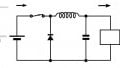
Simplified schematic of MMC showing submodule and half-bridge circuit with a capacitor in one of the submodules. Image used courtesy of the author.
Capacitor Function and Challenges in MMCs
In high-voltage MMCs, each submodule includes a full or half-bridge circuit, and across the DC terminal, the capacitor is connected. The capacitor acts as an energy buffer, storing electric energy to release when there is a demand.
This maintains a smooth and sinusoidal current flow through the converter, preventing extreme current distortion that could destabilize both DC and AC power systems. The stored electrical energy (E) in the submodule capacitor is evaluated by considering the voltage (V) and the capacitance (C) as shown in the formula.
$$E = \frac{1}{2}C V^2$$
Understanding the ability of the capacitor to release and store or absorb energy helps in evaluating how well the submodule in an MMC regulates arm current without causing overvoltage in the converters. For each of the MMC modules, a submodule capacitor can be used to define the voltage contribution.
Since these stacks of submodules synthesize the MMCs' outputs, precise control of the voltage through the capacitor is an essential factor for consideration. Mismatches in the capacitor voltage can result in imbalances between the converters' arms, potentially leading to problems such as distorted AC voltage and increased circulating current.
To mitigate this, the converter's control system should continuously monitor and control the capacitor voltage to ensure stable and balanced operation.
Ripple Power and Energy Storage in Submodules
During AC to DC power conversion, these submodule capacitors also help in filtering the internal ripple power. In MMCs, the oscillation of power flowing through each arm is twice the frequency of the grid. For instance, if the frequency of the grid is 50 Hz, the oscillation doubles to 100 Hz, which generates ripple power that can affect the DC links and AC output. The sub-module capacitors, therefore, prevent voltage propagation by releasing energy at this frequency.
However, it is essential to correctly size these capacitors to maintain acceptable limits of 5-15% of the nominal voltage. This is done by considering the peak ripple power in each submodule (Pripple), the ripples' angular frequency within the grid (ω), the acceptable peak voltage ripple (Δv), and the nominal or average capacitor voltage in the submodule (V).
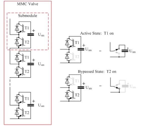
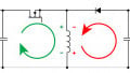
MMC valve operation illustrating energy storage and discharge of capacitor with different switching state of the output. Image used courtesy of Wikimedia.
The instantaneous power fluctuations directly influence the energy storage needs of the submodule capacitor in each converter arm in the MMC. The instantaneous power (p(t)) has two main components: a steady average component and a varying ripple component.
To understand these components, we consider the grid frequency (f), the peak amplitude of the ripple power, and the average transferable DC power supplied by the converter's arm. Accounting for these components is essential to voltage stability across the submodule capacitors, ensuring that the fluctuating energy within the converter periodically discharges and charges smoothly.
$$\rho(t) = P_{avg} + P_{ripple} \cdot \cos (2 \omega t)$$
The peak energy that the submodule capacitor must buffer also determines the capacitor's energy storage capacity. It is evaluated by integrating the ripple power component over one-quarter of its period of oscillation. From the evaluation, a higher storage capacity of the capacitor can handle a greater ripple power, while lower frequency oscillations (ω = 2πf) may cause large energy swings.
With the variation of the capacitor's stored energy with the square of its voltage, the allowable voltage ripple can efficiently govern the selection of a suitable submodule capacitor by considering the nominal voltage with a small symmetric ripple in which this energy variation linked to this ripple can be evaluated as the difference between the energy at V+Δv/2 and V-Δv/2.
If the energy fluctuation due to voltage ripples is:
$$\Delta E = \frac{P_{ripple}}{2 \omega}$$
$$E = \frac{1}{2}C V^2$$
The energy stored in a capacitor can be expressed by expanding the terms with both energies, as shown below:
$$\Delta E = \frac{1}{2} C~[~\, (V + \frac{\Delta v}{2})^2 -(V - \frac{\Delta v}{2})^2 ~]\,$$
Simplify the binomial expression:
$$(V + \frac{\Delta v}{2})^2 -(V - \frac{\Delta v}{2})^2 = 2V \Delta v$$
Taking the difference:
$$\Delta E = \frac{1}{2} C~(2V \Delta v) = CV \Delta v$$
Therefore, in terms of voltage ripple, the change in energy is thus:
$$\Delta E = CV \Delta v$$
The formula can now be equated with the energy ripple needed.
$$\frac{P_{ripple}}{2 \omega} = CV \Delta v$$
The resultant solution for capacitance can therefore be evaluated or solved for as:
$$C = \frac{P_{ripple}}{2 \omega ~ V ~ \Delta V}$$
With the capacitance value accurately sized for the MMC submodule, quantifiable design constraints can therefore be based on ripple limits.
Lifetime Oriented Sizing of Capacitors
Lifetime-based sizing of the MMC's submodule capacitors is essential for ensuring long-term reliability under continuous electrical and thermal stress throughout the converter's operating lifetime. RMS ripple current is one of the most stressful factors on capacitors, as it generates heat while flowing through the capacitor's equivalent series resistance (ESR).
This thermal cycling of the capacitor increases ESR and degrades the dielectric material, which in turn increases the rate at which the capacitor ages. Based on the converter's topology, load profile, and control method, capacitor selection can be evaluated based on the maximum allowable RMS ripple current, ensuring it is not exceeded. This, combined with consideration of manufacturers' specifications, ensures that the temperature remains within permissible limits, typically between 0°C and 15 °C.
In addition to heat, guided by standards such as IEC 61071, which specifies the endurance threshold and test conditions, MMC's power capacitors are typically designed for an operational life of 15-30 years.
Practical Example of 60 kV MMC with 20 Submodules per Arm
To better illustrate lifetime and stress-oriented submodule capacitor sizing, consider an example of a 60 kV MMC system that features 20 submodules per arm. The design requires an equal voltage contribution from each submodule, which is essential for operational stability.
Assuming the frequency of the power is 50 Hz and an allowable voltage ripple of 15%, depending on the system, the capacitor in the MMC can be sized by first considering the voltage in each submodule, which is calculated by dividing the total voltage by the number of submodules.
Assumed parameters for this example:
- Voltage in each submodule (Vsm):
$$V_{sm} = \frac{60 \text{ kV}}{20} = 30 \text{ kV}$$
- Ripple power in each module (Pripple):
$$P_{ripple} = 1.5 \text{ kW}$$
- The allowable voltage ripple (Δv):
$$\Delta v = 0.15 ~\times~V_{sm} = 0.15 ~\times~ 3000 = 450 \text{ V}$$
- Frequency of the grid:
$$f = 50 \text{ Hz}$$
$$\omega = 2\pi f = 2\pi \times50 = 314.16\text{ rad/s}$$
With the above parameters, the capacitance can therefore be evaluated using the energy-based ripple power equation to make the correct choice of submodule capacitor for the example MMC.]
$$C = \frac{P_{ripple}}{2 \omega ~ V_{sm} ~ \Delta V}$$
Substitute the known parameters into the formula:
$$C = \frac{1500}{2 ~\times~ 314.16 ~\times~ 3000 ~\times~ 0.15} = 0.0053 \text{ F} = 5.3 \text{ mF}$$
To compensate for two capacitors per arm in each submodule for symmetric energy swing compensation, we can multiply the resultant capacitance by two to get the capacitance value in the submodule as 10.6 mF.
To finalize, it is essential to now account for aspects such as aging, temperature, and ripple tolerance. This accounting for the final capacitance value to use in the design is achieved by applying an assumed 20% design margin to the evaluated capacitance, which increases the required capacitance from 10.6 mF to 13.25 mF, ensuring endurance through long-term and reliable use, even in the presence of environmental factors.
The capacitance can therefore be evaluated by dividing the theoretical capacitance initially calculated based on voltage ripple, frequency, and power, by the difference of one with the derating factor (D), expressed as a decimal (for example, 0.2 for 20%). The choice of the derating factor to use for your design depends on temperature and voltage stress, manufacturing tolerance, and aging and degradation considerations.
$$C_{design} = \frac{C_{required}}{1 - D}$$
$$C_{design} = \frac{10.6 \text{ mF}}{1 - 0.2} = 13.25 \text{ mF}$$
Design for Stability, Not Just Operation
In MMC submodules, the sizing of capacitors in the modules extends beyond managing voltage ripple, as it directly influences the overall stability of the converter, the long-term balancing capabilities of voltage, and the system's ability to ride through faults and other dynamic conditions.
As MMC systems scale to voltages beyond 100 kV, the simplistic submodule capacitor sizing method becomes inadequate, which may now prompt power engineers to adopt more analytical sizing approaches that include detailed modeling of ripple energy, analysis of ESR loss, and derating for thermal stress compensation.
This analytical capacitor sizing approach ensures that the MMC not only operates reliably but also ensures stable operations in dynamic operating conditions, ultimately preventing premature aging.
Featured image used courtesy of Adobe Stock (licensed).