Facebook
 Google
 GitHub
 Linkedin
Learn About Basic Continuity Testers, Series, and Parallel Ohmmeters
To check a circuit, two of the factors that should be taken into account are continuity and resistance. The test required determines the type of testing device to be used.
The testing of electrical circuits requires that measuring instruments be able to cope with very high and very low values of resistance. What may be suitable for measuring high resistances is not necessarily suitable for measuring low resistances. High-value resistors and insulation testing need one type of device, while low values of resistance and continuity testing need another type.
Low-Value Resistance and Continuity Testers
Low-value resistance testers can range from elementary to quite complex. The choice often depends on the degree of accuracy required.
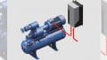
For simple continuity testers, all that is required is a low-voltage source of power and an indicator, for example, a 6V battery and a 6V lamp or buzzer. Two test leads, the lamp, and the battery are connected in series and, when testing a circuit, the continuity of a conductor is indicated when the lamp lights.
This type of tester has the advantage of being simple, easily made up when required, and inexpensive. The disadvantages are that regular battery replacement is required, and the low voltage may not provide sufficient power to give a positive indication when the circuit is complete but contains an appreciable amount of resistance. In this case, the lamp may not light and falsely indicate an open circuit.
Whenever circuits and test equipment indicate a possible fault is present, further testing is necessary. More sophisticated equipment might have to be used to indicate the extent and type of the problem. It may well be that resistance is present in the circuit, giving a doubtful indication. The fault might be more extensive than that, of course, and that is the purpose of the testing function.
One attempt to get around this problem was the introduction of small hand-cranked generating sets used in conjunction with a suitable bell. When the crank was turned, and the test leads touched together, the bell would ring.
The voltage was often around 150V but was also AC. Costlier than a battery and a buzzer, the system was rugged, still relatively simple to use, and operated on low resistances. Excellent for checking out multiple conductors in a new installation, it also had one big disadvantage. Since it worked on AC, its indication was subject to high inductances in the circuit path. No indication would be given under some circumstances.
Ohmmeters
There are two basic types of ohmmeter circuits—series and parallel. The name relates to the position of the unknown resistance in the circuit. A series circuit has the unknown resistor connected in series with the meter. A parallel ohmmeter circuit has the unknown resistor connected in parallel with the meter. Each connection has its own advantages. Both circuits can give continuity checks as well as indicate relative values of resistance. Unlike the continuity testers mentioned above, no audible or visual indication is given. A meter scale has to be read.
Series Ohmmeters
The series circuit is the most common and is shown in Figure 1(a). It consists of a battery, a fixed resistor, and an adjustable resistor. The fixed resistor is a current-limiting resistor to provide some form of protection for the meter. It is often called a ballast resistor.
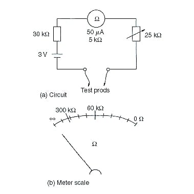
Figure 1. Simplified circuit for a series ohmmeter circuit diagram and meter scale.
Figure 1(b) shows that the meter scale is the reverse of that of a normal scale. Zero ohms (0Ω) is indicated at full-scale deflection and infinity at the zero ends. It should also be noted that the scale is non-linear.
In use, the meter must be adjusted to indicate zero before switching on, and then the probes joined together and the meter adjusted to read full scale. When the probes are open-circuited, the meter reading will fall to zero again. The unknown resistor is then placed in contact with the probes, and the value is read against the meter scale. For the values shown in Figure 1, the meter would indicate a resistance of 60kΩ at half-scale or 25μA meter current. At 10μA, the indicated resistance would be 300kΩ. Both values are shown on the meter scale.
Parallel Ohmmeters
A typical circuit for a parallel ohmmeter is shown in Figure 2(a). It includes a switch to ensure that the battery is not left on when the meter is not in use. This is usually done with some type of trigger or finger-operated switch. The idea is that when the leads are put down, the battery is automatically switched off.
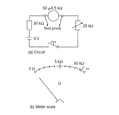
Figure 2. Parallel ohmmeter circuit diagram and meter scale.
The same operating adjustments have to be made for the series meter to ensure that zero and full-scale deflections occur at the correct scale positions. When the probes short out the meter, it should indicate zero. When the probes are open-circuited, the meter should read full-scale deflection.
The meter scale is shown in Figure 2(b). It is also non-linear, but the values progress across the scale in a normal manner. For comparison purposes, the indicated position for the 60 kΩ resistors is marked on the scale at a position corresponding to 46 μA. Half-scale or 25 μA then corresponds to 5kΩ.
The 300kΩ position is not shown but corresponds to a current of 49.2μA. This would be indistinguishable from a full-scale reading. If the two half-scale values are compared, it can be seen that the parallel-type circuit is better suited to lower values of resistance than the series-type circuit.
The parallel-type circuit is less popular and is used for measuring lower values of resistance than the series-type circuit. It does not readily lend itself to being part of a multimeter circuit like the series-type resistance circuit.