Facebook
 Google
 GitHub
 Linkedin
How to Safely Achieve High-Accuracy Testing Results in High-Voltage Measurement
This article features Vitrek, LLC proper application of high-voltage probes and the basic functions and features of the meter for flexibility in application.
One of the first principals learned as an engineering student is the “observer effect” which states that simply observing a situation or phenomenon necessarily changes that phenomenon. Accurate high-voltage measurement is a clear example of the validity of this theory.
The accuracy of the resulting measurements is affected by three important elements:
- environmental factors,
- errors that are introduced by the measurement probe, and
- the intrinsic accuracy and performance of the measuring instrument.
This article will address each of these areas with the objective of providing guidance in safely achieving optimum accuracy in making high-voltage measurements.
High-Voltage Applications
For the purposes of this article, “high-voltage” is defined as 1 KV to 150 KV, either AC or DC. Accurate high-voltage measurement is essential in design and manufacturing of a remarkably wide range of applications:
- Analytical instruments (Mass Spectrometry, Photomultiplier tubes, others)
- Defense and Aerospace (Radar, CRT, Simulators)
- Homeland Security (Explosive Detection Systems (EDS), Explosive Trace Detection (ETD), Baggage Inspection, X-Ray Inspection)
- Inspection & Non-Destructive Testing Systems
- Manufacturing Processes (Electron Beam Welding, Electrostatic Coatings, Induction Heating, Crystal Pulling, Capacitor Charging, Photoreceptor Corona Charging, others)
- Medical & Biotechnology (X-Ray, Radiography, Electrophoresis, others); Pulsed (Laser, Capacitor Charging, Sonar, others)
- Research Laboratories (Detectors, Accelerators, Nuclear Instrumentation, Electrophotography, others)
- Semiconductor Equipment (Ion Implantation, Sputtering, Epitaxy, Deposition, Electrostatic Deflection, Plasma Diffusion, Plasma Chemical Vapor Deposition, others);
- High Voltage Power Supplies
- RF Generators and Matching Networks
- High Voltage Amplifiers
- Electrical Distribution (Corona Detection, Cable Insulation Testing)
Accurate high-voltage measurement is needed in all of these applications and in the calibration labs used to maintain these instruments.
Environmental Factors
High voltage measurements are susceptible to errors and to environmental factors. At elevated voltages, electromagnetic effects must be taken into account. Just walking past the measurement setup can cause errors. The Operator’s Manual for the Vitrek 4700 Precision High Voltage Meter provides insights into the importance of a controlled environment:
The instrument should not be used in an environment where conductive pollution can occur, e.g., in an outdoor environment.
- If fluids or other conductive materials are allowed to enter the unit enclosure, even if not powered, the unit should be taken out of operation and services as safety may have been compromised.
- If the unit is transported between differing environments and condensation is suspected, the unit should remain unpowered for the condensation to be dissipated.
- When AC voltages are present, even if there is sufficient insulation in the connections, there may be significant capacitive coupling which can cause an unsafe current to flow into nearby objects. Corona may occur even outside the insulation. These effects are made worse by sharp corners. In severe cases, corona can cause interference with the measurements and will reduce the capabilities of the wiring insulation over time, eventually resulting in insulation failure.
Rules regarding the location of the probe must also be carefully followed: As an example, for Vitrek’s 35 KV SmartProbe, the manual makes this prescription: Full accuracy specifications are valid assuming that there are no objects within a cylinder of radius 18” centered on the probe body extending from the handle (or base) to a point 6” beyond the probe tip. The connection to the probe tip is assumed to extend from the probe tip in line with the probe for at least 6”.
Typically, the effect of a hand-sized grounded object is <0.01% at 60Hz when placed 4” from the probe and <0.1% at 400Hz when placed 18” from the probe. As long as objects do not move relative to the probe, there is negligible effect on DC measurements caused by nearby objects. Objects generating fields may need to be placed further away from the probe. At higher voltages, the radius increases. For the 150 KV probe the radius of the cylinder increases to 48”.
Measurement Probe Effects
Most high-voltage meters are capable of making direct measurements (with a handheld probe) for up to 1KV, while others can handle direct measurement up to 10 KV. In consideration of the hazard potential, use of a hand-held probe comes with a serious warning like this: WARNING – The instrument measures high voltages on the direct terminal. These voltages can cause severe injury or death. The user must ensure that connections have sufficient insulation. Even when sufficient insulation is present, the user should not put any part of their body in proximity to the connections while high voltages are present (at least 1 in per KV is recommended). The user should not insert or remove any connections when high voltages are present. WARNING – Do not apply high voltages to a probe without it being properly plugged into the meter.
Measuring High Voltages with External Probes
When measuring higher voltages, an external probe is used. The most common type of probe utilizes the method prescribed in a NIST document with details on utilizing a voltage divider network to reduce the voltage applied to the meter to within its basic input range (Figure 1). The voltage divider is comprised of a series of identical precision resistors. For example, a 100:1 voltage divider would allow an instrument with a 1 KV max input to measure an applied voltage of up to 100 KV.

Figure 1: A voltage divider is typically used to measure voltages above the instrument’s direct input range.
The voltage divider is comprised of a large number of precision resistors in order to limit the error and uncertainty. The series of carefully matched resistors would (theoretically) eliminate errors from self-heating or other factors that would affect the resistor string in a uniform fashion. Even so, there remain a number of contributing factors to error and uncertainty:
- Resistance variation from one resistor to another
- Variations (although minor) in temperature coefficient
- Electromagnetic effects
- Capacitance effects
In order to mitigate these effects, a series resistor voltage divider would typically take on a configuration like the one shown in Figure 2. The resistors in the array would be arranged in a helical fashion to reduce errors from electromagnetic and thermal factors.

Figure 2: 100:1 voltage divider network built in compliance with the NIST standard.
The voltage divider network is susceptible to a number of error-producing effects, among them, self-heating, capacitance effects on AC measurements and electromagnetic effects. Voltage divider probes must be calibrated with the meter. Calibration should also identify sources of uncertainty.
As stated in one manufacturer’s materials:
“For highest accuracy in high impedance, low input capacitance types, consideration must be given to induced voltage pick-up in leads, contact potential, corona, effective capacitance, and voltage gradient and capacitance shift related to proximity to high voltage sources, ground planes, walls, enclosures, and loads. Preferably the divider should be calibrated with the specific instrument being used and specific proximities if extreme accuracy is required, Greatest accuracy, particularly AC accuracy, is attained with proper ground plane and if maximum clearance to conductive materials, which can cause capacitance variation and corona. If available, user’s proximity dimensions will be simulated when calibrating.”

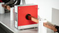
Figure 3: Vitrek’s 4700 Meter measures microamperes using high voltage SmartProbes
An alternative, and perhaps more elegant solution is to connect the source to a single high resistance and measure the microampere current. This, of course, requires the precision “voltmeter” to also operate as a, low-impedance, precision ammeter. For example, this alternative is utilized with Vitrek’s high-voltage Smart Probes (Figure 3). Unlike voltage dividers that must be calibrated with the meter, these smart Probes include calibration data that is automatically updated when the probe is connected to any Vitrek 4700 meter. Comparison of the performance of these alternative approaches is difficult because it involves so many factors including the environment, the test setup (including impedance matching) and the basic accuracy of the instruments. But it can be said that the integrated system approach is vastly better at dealing with the range of errors that have been discussed in this article.
Meter Performance & Accuracy
Most precision high-voltage meters are capable of direct measurement; i.e., without requiring an attenuating probe, for voltages of up to 1000V. An example of this type of meter is the Fluke 8846A 6.5-digit precision multimeter. Meters like this typically have a measurement range of 100mV to 1000V with excellent accuracy specs. However, for voltages between 1000V and 10 KV, meters in this class must utilize an external probe.
A great many high voltage measurements (both AC and DC) are found in the “lower” high-voltage range of greater than 1000V and less than 10KV. Examples of devices that can accommodate direct input within this voltage range are the Kikisui 149-10A and the Vitrek 4700.
Conclusion
Precision high-voltage measurements require careful attention to the environmental conditions, the proper application of high-voltage probes and the basic functions and features of the meter. Careful selection of a highly functional meter can provide both flexibility in application and reduce the need for multiple meters.
About the Author
Chad Clark holds a BA in Business Economics at California State University, Long Beach. He currently works as the Sales Manager at Vitrek since August 2008.
This article originally appeared in the Bodo’s Power Systems magazine.