Facebook
 Google
 GitHub
 Linkedin
How to Reduce up to 20 Percent of Power Loss in Cordless Power Tools
This article features an investigation on the feasibility of replacing TO-220 package MOSFETs with a much smaller SuperSO8 package MOSFET
In recent years power tool manufacturers have continuously increased the power output and improved the performance of cordless power tools. Traditionally, a brushed DC motor was a preferred choice of motor, but advances in MOSFET technology have made the use of Brushless DC Motors (BLDCMs) possible. In order to improve the performance of the power tools, a better motor dynamic and higher output torque from the BLDCM is required. Since the torque of the motor is directly proportional to the motor current, this requirement can only be achieved if the power stage can deliver the necessary current.
Cost optimization of BLDCM solution
The advantages of BLDCM over brushed motors are a higher output power density, better performance, and no required maintenance. These advantages, however, come with an increased cost. If it is to compete with the low-cost brushed DC motor solution, a BLDCM needs to be cost- and size-optimized in order to reduce the large price gap.
Cordless power tool manufacturers who choose BLDCM technology often struggle to implement such low-cost and size-optimized solutions. In the case of the associated MOSFETs, for example, a TO-220 has been the package of choice due to its large size and superior thermal performance over SMD alternatives. If smaller SMD MOSFETs are to be used they have to be more efficient and make the best use of heatsinks. The cooling of surface mount MOSFETs presents the most challenging aspect in the implementation of the SMD devices.
An effective cooling concept, combined with a best-in-class BSC010N04LSI 40V/1mΩ SuperSO8 package with integrated Schottky-like diode, allows designers to switch from TO-220 to SMD packages, thereby reducing cost, increasing inverter power density, and improving tool performance.

Figure 1: Typical phase current waveform; 61.3A_RMS, 100% duty cycle; red triangle – diode conduction
In the application of BLDC motors with block commutation, the RDS(ON) of a MOSFET, as well as the body diode can significantly reduce overall power losses. A lower body diode forward voltage drop of the BSC010N04LSI reduces overall power losses.
In a typical 18V cordless power tool featuring a BLDCM a short burst in excess of 200A phase current is possible. Only the lowest RDS(ON) and a rugged diode can withstand such a high peak current. In order to better explain the circuit operation, a typical phase current in a 3 phase BLDCM is given in figure 1.
By circuit analysis and the switching patterns of the switching devices, we can identify the MOSFET’s body diode conduction portion (the red triangle) and the brackets indicating the conduction time of the diode (red bracket) and MOSFET conduction time (green bracket).
At the high output power of ~1kW, the diode conduction time can reach several hundred µ-seconds. Due to its rather long conduction time, the diode power losses are significant and can be reduced by reducing the VSD as in the case of a Schottky-like diode.
Conduction power losses can be calculated using the following formulae:
(Diode conduction loss)
(MOSFET conduction loss)
Let’s assume that the instantaneous diode current Is=50A, and take typical values for diode forward voltage drop VSD=1V for a standard diode, and VSD=0.6V for a Schottky-like diode
Hence we get:
In case of a normal body diode
In case of a Schottky-like diode
In case of a MOSFET channel
From the calculation above it is evident that the instantaneous diode losses are much higher and that its prolonged conduction time contributes greatly to overall power loss. By reducing the VSD, we can reduce the diode conduction loss.
It should be noted, that the diode conduction current shown in fig.1 is present during the phase commutation (here PWM duty cycle = 100%). During the phase commutation the phase current, which is turned off, has to decay to 0A through the body diode of the MOSFET. Another occurrence of the body diode conduction is during synchronous rectification dead time (when PWM duty cycle < 100%), a mode which will not be further discussed in this paper.
Implementation
The 3 phase inverter, which is required to drive a BLDCM, can be implemented by using two parallel BSC010N04LSI MOSFETs per switch (a total of 12 MOSFETs) on a surface area of 45mm x 36mm.

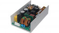
Figure 2: 1kW power stage B6 built with 12 BSC010N04LSI underneath the copper plates cooling structure
The PCB uses a special copper plate arrangement that allows effective heat dissipation from the SMD MOSFETs, and at the same time provides the required battery connections and motor output connections. The copper plates measure 8mm in height and are placed on the same PCB area, thereby resulting in an overall volume of 13cm3.
Using these copper plates eliminates the need for high-current copper traces on the PCB since the high current (in excess of 200A) is conducted only through the copper plates.
A complete power stage, together with XMC microcontroller demonstrates the performance of this solution. A power level of 1kW (20V/50A) can be easily achieved.
Experimental Results
The efficiency of the inverter is measured for both the BSC010N04LS and BSC010N04LSI (see fig.3). Under same test conditions the BSC010N04LSI power losses are reduced by up to 20 percent indicating a clear advantage due to the Schottky-like diode.

Figure 3: Power loss of the BSC010N04LS (blue trace) vs. BSC010N04LSI (red trace)
Conclusion
In this article we investigated the feasibility of replacing TO-220 package MOSFETs with a much smaller SuperSO8 package MOSFET. A combination of low RDS(on) and a Schottky-like diode allows the implementation of the SMD solution. It is shown that the Schottkylike diode at maximum output power can reduce power losses by up to 20 percent. This reduced power loss is directly proportional to a temperature reduction of the MOSFETs. Infineon’s OptiMOS™ BSC010N04LSI MOSFET with a monolithic Schottky-like diode is the best choice for block commutated high-speed BLDC motors employed in cordless power tools.
About the Author
Elvir Kahrimanovic works as the Systems Applications Engineer at Infineon Technologies since July 2013, world leader in semiconductor solutions that make life easier, safer and greener.