Grounding for Noise Reduction in Electronic Systems
Learn about everyday grounding systems to reduce common-mode noise.
Grounding is the primary method of reducing noise pickup. A good grounding and bonding design can solve a considerable percentage of noise problems.
Isolated Ground (IG) Systems
When disturbances like EMI, RFI, or electrical impulses caused by welders, variable speed drives, appliances, and others, are present in the grounding system, they create common-mode noise between neutral and ground that may affect electronic equipment.
The National Electrical Code (NEC) permits the installation of isolated ground receptacles (IG), i.e., no connection between the yoke and the grounding terminal. Yoke is the metal frame behind the receptacle that is used to fix the device to the outlet box.
An IG system’s ideal objective is to provide low neutral-to-ground voltages in the electronic equipment’s AC input This prevents the noise from passing through the logic circuitry and corrupting the processed data.
When properly installed, the neutral to the isolated ground voltage (noise) should be lower than from neutral to the metallic conduit.
But there is nothing isolated in this grounding arrangement. The isolated equipment grounding conductor (EGC) provides a low impedance path for the ground-fault current flow between the receptacle grounding terminal and the neutral in the service equipment or the secondary of a separately derived system (e.g., an isolation transformer). The isolated EGC, and not the conduit, is the safety ground for the electronic equipment – the only route for the fault current to return to the source. Green insulation with a longitudinal yellow stripe identifies the isolated EGC.
The receptacle’s metal frame must be grounded. The receptacle’s frame has separate ground connections bonded to the general ground system through the metallic conduit, an insulated – the green wire – or bare equipment grounding conductor run with the circuit conductors, or another wiring method that serves as an EGC.
The NEC allows the isolated EGC to pass through several subpanels without connection to the grounding bus. As a practical matter, the isolated EGC may terminate at the subpanel where the noise attains an acceptable level.
Figure 1 shows an isolated ground system supplying data processing (DP) electronic equipment.
Figure 1. IG system supplying DP equipment.
The metal raceway is grounded, employing a connection to the service equipment enclosure. The isolated EGC, connected to the service equipment’s neutral, passes through the downstream panelboard and terminates in the electronic equipment cabinet. The NEC permits the equipment cabinet’s isolation from the raceway containing the supply conductors, using nonmetallic raceway fittings.
When the electronic equipment manufacturer specifies an isolated ground for the equipment, they usually do not provide an isolated ground terminal for that purpose. There is only one ground terminal attached to the AC power supply, chassis, cabinet, and zero reference. In this case, the safety ground – green or bare wire – should not be connected to that ground terminal. The equipment cabinet should be isolated from the ground and other metals in contact with the safety ground to keep the isolated EGC as the only path for ground-fault current.
Power to electronic equipment should not share a common branch circuit supplying noise-generating devices. For example, feeding a copier – with motors and heaters – from the same circuit will inject high-frequency noise into the grounding system, disrupting the electronic equipment operation. If the copier requires an IG system because it has microprocessor-based circuitry, it should be connected to separate branches. Not to mention powering coffee makers, clocks, radios, vacuum cleaners, electric drills, and other noise-generating devices.
An important fact is that IGs do not always enhance the equipment’s performance.
Shielded Isolation Transformers
Sometimes there is a long separation between the main service equipment and the electronic equipment, resulting in a long EGC between the electronic equipment and the connection to the ground in the power source. The long wire will have a relatively high impedance, reducing the fault current – needed to open circuit breakers and melt fuses – and increasing the time for fuses and circuit breakers to clear faults. Also, recalling that noise currents circulate through the EGC, the augmented impedance will develop larger noise voltages.
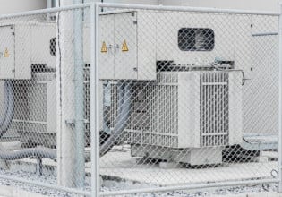
One way of shortening the EGC and reducing the above effects is by installing a shielded isolation transformer near the electronic equipment and its panelboard. The shielded isolation transformer has excellent insulation between its primary and secondary windings, taking the main service equipment grounded neutral out of the picture and restoring the ground at the secondary winding.
Bonding the EGC to the new, closer ground will make a better return path for fault currents and reduce common-mode noise.
Figure 2 shows a diagram of a shielded isolation transformer.
Figure 2. Shielded isolation transformer for electronic equipment.
A Practical Arrangement to Reduce Common-mode Noise
Figure 3 shows a practical arrangement to supply power to plug in electronic equipment, like a set of personal computers and peripherals, using the IG principle. This arrangement should provide an acceptable common-mode noise rejection level.
Figure 3. Grounding using an IG receptacle.
The power source is a shielded isolation transformer close to the panelboard reducing the wire length and noise. The transformer’s shield rejects a lot of high-frequency noise.
According to the NEC, the isolation transformer qualifies as a separately derived system – the neutral is not carried through from the input to the output – requiring a neutral-to-ground bond at the low voltage side. This bond provides a zero-volt reference to the electronic equipment.
The isolated EGC runs from the isolated-ground-type receptacles – powering the electronic equipment – directly to the isolation transformer’s neutral-to-ground bond through the conduit. The EGC may pass through subpanels without connection to the equipment metal frame grounding bus. Bond the metal conduit carrying the isolated EGC to the enclosures at both ends. The NEC requires all wires originating at the secondary winding – phase, neutral, isolated EGC, and green wire when used – to run in the same conduit.
This arrangement reduces troubles when there is a connection between the peripheral and the computers’ grounding system through the data wire’s shield.
Signal Reference Structures in Data Processing Rooms
It is usual to employ a signal reference structure (SRS) to establish a ground reference to the electronic equipment placed in computer installations and control rooms, reducing the common-mode noise.
The SRS equalizes the ground potential from DC to the megahertz range. It provides numerous parallel grounding paths avoiding resonance conditions. Resonance occurs when the length of a ground path matches a multiple of a quarter wavelength of the frequency in use – causing the lead to behave as an open circuit.
The SRS may be in the form of a signal reference plane or a signal reference grid. The signal reference grid is more economical and typically employs the room-raised floor’s support structures.
A raised floor consists of a grid of metal stringers supported by metal pedestals. The floor tiles are sections of particular flooring that drop into the stringers. The tiles’ top side is a low conductivity material, providing isolation to the equipment cabinets resting directly on them but allowing the discharge of the static electricity generated by personnel. The tiles’ bottom is a copper grid making good contact with the supporting structure. The metal stringers are bonded, creating a ground plane.
Underneath the raised floor are the branch-circuit conductors, power supply cords, communications, data, grounding, connecting, and interconnecting cables, the cord-and-plug connections, and the receptacles associated with the electronic equipment.
The NEC permits the use of an SRS, connected to the equipment grounding conductor – green or bare wire – provided to the electronic equipment. Bond the pipes, steel structure, and other metallic parts entering the room to the metal stringers, either directly or through a ground ring.
Figure 4 shows a typical signal reference grid arrangement in a raised floor. In this figure, SRG refers to the signal reference grid.
Figure 4. Typical SRG using the raised floor.
The room’s cabinets may be grounded to a single point, typically the grounding bar in the AC panel supplying power to the cabinets. The AC grounding bar is the single point ground for the power wiring and the cabinets.
An excellent option is placing the power source inside the room – e.g., an isolation transformer – grounded within or at the room’s periphery. Computer power centers are complete assemblies to supply branch circuits to data processing equipment, with control, monitoring, and alarm functions.
Short leads connect the isolation transformer’s secondary neutral, all signal grounds, and cabinets to the signal reference grid.
Figure 5 shows typical ground connections in a data processing room.
Figure 5. DP equipment connected to AC power source ground and SRG.
An Overview of Grounding for Noise Reduction in Electronic Systems
The NEC allows an isolated equipment grounding conductor to provide a noise-free, zero-volt reference in electronic systems having microprocessors.
The isolated EGC runs from the neutral/ground junction point (main bonding jumper) on the service equipment, or a separately derived source, to the electronic equipment or isolated receptacles.
The isolated EGC – green wire with yellow stripes – must be installed with the phase, neutral, and safety ground – green wire – conductors in the same conduit and can pass through subpanels without connection to the grounding bus. Any of the approved wiring methods must ground the IG receptacle’s metal enclosure.
Advantageously, an electronic equipment room receives power from a dedicated transformer, like an isolation transformer. The isolation transformer may be shielded and is useful for common-mode noise attenuation. Its primary function is to provide a separate energy source at the closest point to the electronic equipment and isolate it from other energy sources on the premises.
The transformer’s neutral-ground bond serves as a single point for all grounds in the electronic equipment room.
A signal reference grid supplies an equipotential plane for a broad frequency band, providing multiple paths between its parts. If one direction is high impedance due to resonance, other ways of different lengths provide a low impedance route with negligible potential differences between any two points on the grid. The result is a practical equipotential reference for signals from DC to the megahertz range.


