Facebook
 Google
 GitHub
 Linkedin
Solving Military-Avionics DC-DC Power Challenges with Modularity—Part 1
We begin this article series on understanding standard parameters and best practices for the effective design of aerospace and military-grade power supplies. Part 1 examines key stress limits.
This article is published by EEPower as part of an exclusive digital content partnership with Bodo’s Power Systems.
While power electronics designers are skilled at designing power supplies, they often lack the knowledge necessary to meet military or aerospace standards. This series of four articles provides guidance to help designers understand standard parameters and presents best practices for the effective design of aerospace and military-grade power supplies. This first part provides a comprehensive list of key stress limits, which will serve as an essential technical reference.
A Need for More Powertful Power Supplies
Military and avionics applications demand more powerful power supplies. This is mainly due to two factors: first, many functions that were in the past performed using mechanical or hydraulic methods are now fully electric; and second, emerging technologies such as high-power processing like mission-critical computers, software-defined radars, directed-energy weapons (DEW), or any AI-based electronic device require significantly more energy.
This increase in demand for electrical energy is illustrated by the following examples: the Dassault Mirage F1 was equipped with 2 15 kVA electrical generators [1.1], whereas the new Dassault Rafale is equipped with an 80 kVA generator [1.2]. In another example, the F16 Fighting Falcon uses a 40 /60 KVA [1.3] generator, while the latest F35 Lightning II is equipped with a system that can generate up to 160 kVA [1.4]. Military vehicles are also keeping pace, with hybridization leading to increasingly powerful electric power sources.
Image used courtesy of Adobe Stock
Given these figures, it is not surprising that electronic design engineers are required to produce new projects following the SWaP (Size, Weight, and Power) trend for lower size, lower weight, and higher power. The challenge of developing modern applications is also exacerbated by the fact that power supplies must comply with stringent standards. In most cases, leveraging a modular power architecture based on COTS (Commercial Off-The-Shelf) components remains the simplest and most effective approach.
This article will provide a comprehensive review of standards to design power supplies for military and avionic applications, and suggest some examples of functions designed with discrete components, and their counterpart using COTS-based modular power supplies such as those proposed by Gaia Converter.
Table 1. The main standards relevant to the design of military or aerospace power supplies are listed in this table with their main purpose and latest revision for 2025. Image used courtesy of Bodo’s Power Systems [PDF]
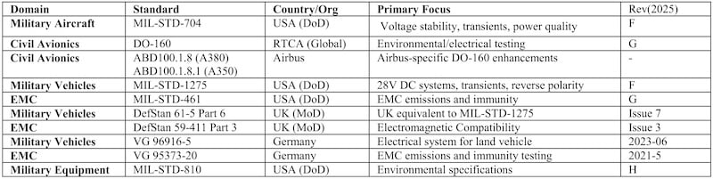
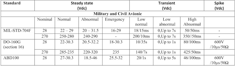
Table 2. The voltage specifications for military and civil avionics power supply buses are defined in the three main standards above, with voltage ranges under different conditions, as well as transient voltages. Image used courtesy of Bodo’s Power Systems [PDF]
Military and Avionic Standards
The following standards specify the key electrical and environmental requirements for designing military and avionics power supplies:
- MIL-STD-704: Aircraft Electrical Power Characteristics, which defines the requirements for DC and AC electrical buses in military aircraft. This document can be used in conjunction with the MILHdbk-704 handbook, providing guidance for the test procedure.
- RTCA DO160: Environmental Conditions and Test Procedures for Airborne Equipment. Dedicated to civilian avionics, this standard describes both the electrical and environmental conditions for civilian avionics. The avionic bus voltage limits, along with conducted and radiated electrical noise and susceptibility, are also described.
- ABD100: Counterpart of DO160, this standard is dedicated to Airbus aircraft exclusively.
- MIL-STD-1275: Characteristics of 28 VDC input power to utilization equipment in military vehicles. Applicable to all electronic devices onboard military vehicles. This standard defines limits for 14 and 28 VDC bus voltage.
- Mil-STD-461: requirement for the control of electromagnetic interference characteristics of subsystems and equipment. This standard defines the EMC rules for military equipment.
- Defstand 61-5 part 6: 28 VDC Electrical Systems in Military Vehicles, similar to MILSTD-1275, released by the British Ministry of Defense.
- Defstand 59-411 part 03: Electromagnetic Compatibility Test Methods and Limits for Equipment and Subsystems. Released by the British Ministry of Defense, similar to MIL-STD-461.
- VG 96916-5 Electrical system for land vehicle, DC networks, technical specification requirements for electrical systems, and compliance test on system and component level. Also similar to MIL-STD-1275, this standard is released by the German Institute of Standards for Germany.
- The VG 95373 Electromagnetic compatibility (EMC). It defines the limit for conducted emission, while (VG 95373-20) covers conducted susceptibility, and VG 95373-24 deals with the limit for conducted emissions (current).
- MIL-STD-810 Environmental engineering considerations and laboratory test that defines mechanical and cycling test procedures and specifications.
Table 3. The standards applicable to military vehicle equipment define the voltage range, surges, and other disturbances. Image used courtesy of Bodo’s Power Systems [PDF]
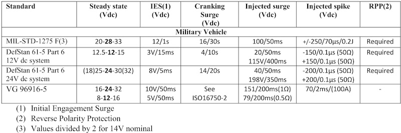
Table 4. The Mil-STD-461 defines multiple electromagnetic interference disturbances that are defined according to multiple waveforms and levels. Image used courtesy of Bodo’s Power Systems [PDF]
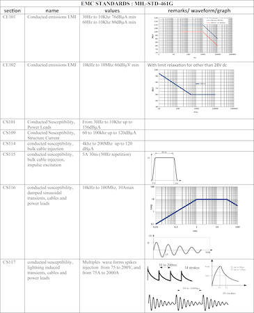
One challenge in military power supply design is efficiently locating relevant parameters within extensive standards documents. Tables 2 to 6 provide a concise overview of the main parameters that DC/DC power supply designers must consider in relevant standards. Although these tables are not exhaustive, some requirements, like limited inrush current, isolation voltage, or load dump, are not described.
Section markers and waveform diagrams for EMC standards help identify parameters and serve as preliminary guides before consulting the full standard. It is essential to consult the complete standard document before beginning the design for several reasons:
- Older revisions of a standard may have different limit values.
- Many parameters cannot be fully described by numbers alone; they require curves and detailed explanations for proper context.
- Standards often include descriptions of test fixtures and setup diagrams, which are crucial for understanding how parameters are measured and applied.
Table 5. The EMC requirements for civil aviation equipment are covered by sections 17 to 23 of DO-160G. Image used courtesy of Bodo’s Power Systems [PDF]
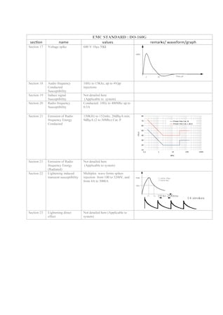
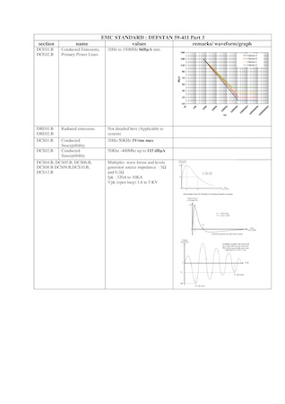
Table 6. The UK Ministry of Defense has published a document named DEFTSAND 59-411 Part 3, which defines the disturbance limits for electromagnetic compatibility of equipment and subsystems. Image used courtesy of Bodo’s Power Systems [PDF]
By referring directly to the full standard, designers ensure they account for the most current requirements and fully understand the test conditions associated with each parameter
Table 4 and 5 describe EMC requirements from the most well-known reference documents, MIL-STD-461 and DO-160. However, standards released by European countries, such as the UK’s DEFSTAN 59-411 and Germany’s VG 95373-20 series, are also worth considering. For some equipment categories, these standards feature more aggressive specifications than their MILSTD counterparts.
This is particularly the case for conducted EMI on primary power lines, where limits for Class A equipment extend down to 0 dBµA, as shown in Table 6. The parameters of VG 95373-20 are not described in this article and follow a similar philosophy to DEFSTAN 59-411. Readers are invited to consult directly the VG 95373- 20 document for further details.
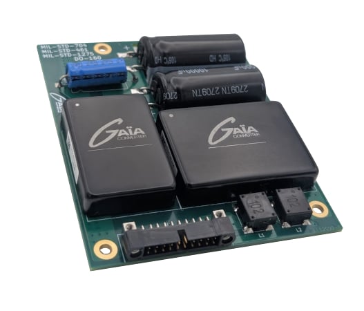
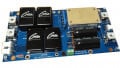
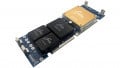
Figure 1. This 40 W power supply complies with Mil-STD704,Mil-STD-461, Mil-STD-1275, and DO 160 standards thanks to its FLHG60, the latest integrated input front-end from Gaia Converter. Image used courtesy of Bodo’s Power Systems [PDF]
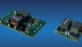
The parameter values in standards like DO160 and VG 96916-5 can seem daunting, such as a 600 V spike or a 151 V surge on a 28 V supply. However, these extreme transients can be clamped with straightforward circuits. Using Gaia Converter commercial off-the-shelf (COTS) transient limiters simplifies this further.
Clamping, EMI and examples
Subsequent articles will demonstrate these clamping methods (Part 2), dive into EMI containment (Part 3), and conclude by presenting examples from Gaia Converter‘s modular power architecture designed for full compliance with these aggressive standards (Part 4).
[1.1] https://www.globalsecurity.org/ military/world/europe/mirage-f1- variants.htm
[1.2] https://web.safran-group.com/ safran-on-board/en/rafale.html
[1.3] https://goallclear.com/wp-content/ uploads/2024/02/AC_OEM_Collins_ F16_EPS.pdf
[1.4] NEXT GENERATION AIRPLANE ELECTRICAL POWER SYSTEMS Nguyen Viet Nguyen B.S., University of Washington, Seattle, 2002.
This article originally appeared in Bodo’s Power Systems [PDF] magazine.