Facebook
 Google
 GitHub
 Linkedin
Floating Measurements with Fast Common Modes and Isolated Probes
Current modern power electronics systems rely on stacked topologies which inevitably lead to the need to measure signals that ride on fast common-mode transients. Fiber isolated probes allow the measurement of such signals but, still, some pitfalls do exist.
Traditionally, engineers have faced the need to measure ground-referenced signals. The principles to increase signal integrity are well known, such as keeping connections short and avoiding areas in between conductors in which magnetic flux can create distortion.
However, the real challenge comes when common modes are present and actually the measurement becomes more difficult as the common mode transient is faster. Probes meant to be floated have a finite CMRR and the common-mode voltage will always show up at the output interfering with the differential measurement. Fiber isolated probes currently offer the best CMRR but still not everything depends on the probe and the measurement setup makes a great difference. All measurements seen in this article are taken with the ISOVP fiber isolated probe from Saker.
Fast Pulse with no Common Mode
First, a square step with a rise-time of 4.5ns and no common mode present is measured with wires 4cm in length before connecting the coaxial cable that connects to the ISOVP probe. The measurement is done at the 50Ohm termination. Figure 1 shows the setup and the measured signal. Even though the measurement setup is less than perfect in that we are using 4cm wires to measure this fast signal the measure is still faithful enough and distortion is not huge a problem.

Figure 1. Pulse measured with wires 4cm in length, no common mode. Some ringing in CH2 is seen compared to the original undistorted pulse (upper trace). Image used courtesy of Bodo’s Power Systems
Measurements of Signals in Fast Common Modes
In this case, we use a small battery oscillator (based on an LTC6907) that is connected to the drain of a Mosfet which provides the common-mode voltage change necessary for the measurements. This oscillator board has an SMB output but we will solder the cables directly to the board for this test. The differential measurement is the output of the oscillator, a 2V level signal which is not in sync with the switching of the Mosfet. First, we measure this signal using the same 4 cm long wires as before. Figure 2 shows the schematic and the falling drain voltage (200V in 7ns) together with the oscillator output. The scope is set in persistence mode so that multiple sweeps can be observed. There is a huge distortion seen at the CH2 at the moment of switching in CH1, so what is happening? The fiber isolated probe is supposed to eliminate the contribution of the common-mode voltage, isn’t it?

Figure 2. Oscillator riding on top of MOSFET drain. CH1 is the 200V 7ns common-mode and CH2 is the measured oscillator output with 4 cm long cables. Image used courtesy of Bodo’s Power Systems
The same measurement with wires 1cm in length instead of 4cm brings some improvement but still the distortion is too large. So finally we can make use of the output SMB connector in the oscillator and make a direct connection from oscillator to probe. This gives the lowest distortion possible as seen in Figure 3. Again the scope is set to persistence mode so that multiple switchings can be observed. This result closely matches the CMRR of the optical probe: a 200V 7ns has a fundamental frequency at 50MHz and the CMRR at this frequency is around 67dB. 200V with a 67dB attenuation results in 90mV.
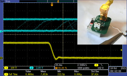
Figure 3. Oscillator connected to probe with SMB connector. CH2 shows negligible to no distortion. Image used courtesy of Bodo’s Power Systems
Practical Example
A fast measurement is made with an Infineon GaN evaluation board on the high side driver (model EVAL_1EDF_G1B_HB_GAN). The board uses a pair of EiceDRIVER (1EDF5673K) gate drivers for the GaN transistors (IGOT60R070D1). A resistive load is used to increase the switching speed of the common mode on purpose. The measurement result follows what should be expected. The spikes at the switching transitions are not due to CMRR limitation of the probe, but due to the divider created by Crss and Ciss in the high side transistor. Note that a coaxial connection is what makes this fast measurement free from ringing and more accurate.
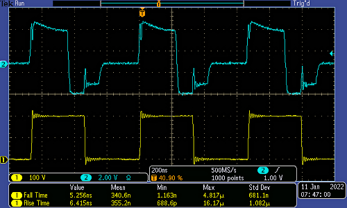
Figure 4. High side gate measurement of a GaN driver switching at 1.5 MHz. Oscilloscope set to averaging mode to reduce noise. Image used courtesy of Bodo’s Power Systems
Simulation
So what is happening? Clearly, the introduction of common modes influences the distortion in a much greater way than differential signal transition speed. Simulation brings some light into the problem. The critical parameters are the source impedance, the parasitic capacitance to the ground of the center conductor, and the length of this conductor as it increases its series inductance. The source resistance together with the cable self-inductance and parasitic capacitances form a resonant circuit that is fed with the common-mode voltage swing. The higher the values of any of them the worst will be the distortion of the measurement. The source resistance is normally given by the device under test (DUT) in question and the cable inductance is dependent on the length of the cable used which can only be so short. So, in practice, the best way to reduce the output distortion is to eliminate the parasitic capacitance present by using a coaxial cable all the way into the DUT.

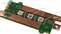
Figure 5. ISOVP connected to the Infineon GaN eval board. Note the direct coaxial connection. Image used courtesy of Bodo’s Power Systems
Conclusion
Fiber isolated probes allow the accurate measurement of signals riding in fast common modes due to their improved CMRR compared to differential probes. However, some additional precautions need to be taken in the measurement setup; otherwise, the CMRR will be ruined. The center conductor in the coaxial input of the probe needs to be protected from external electric fields, and thus it is important to minimize the length of the center conductor in a coaxial cable exposed without shielding.
This article originally appeared in Bodo’s Power Systems magazine.