Facebook
 Google
 GitHub
 Linkedin
EU Cracks Down on Standby Power: Meeting New 2025 Regulations
Device manufacturers are compelled to design products that reduce standby power consumption within strict new limits, but this effort doesn't have to be complicated or expensive. This article examines a simple IC added to an AC-DC power converter that can yield substantial savings in power consumption.
This article is published by EEPower as part of an exclusive digital content partnership with Bodo’s Power Systems.
According to European Union research, the annual energy consumption of household equipment in off or standby mode was estimated at 59.4 TWh in 2015. This power wastage caused the emission of 23.8 million tonnes of CO2-equivalent greenhouse gases.
In tune with the European Commission’s (EC) commitment to making Europe a climate-neutral continent by 2050, new regulations in 2025 will clamp down on the amount of power that almost all types of domestic electronics equipment are allowed to dissipate when off or in standby mode. Device manufacturers must design products that reduce standby power consumption within these limits.
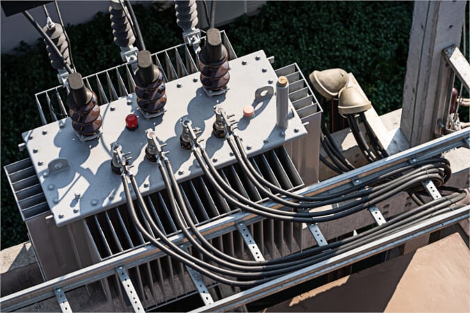
Image used courtesy of Adobe Stock
Ecodesign Requirements
The EC’s new regulation 2023/826 on standby power comes into effect on May 9, 2025. Its goal is to cut annual energy consumption in Europe by 4 TWh. This ambitious target will be achieved by regulating the power consumption of a wide range of household products and office equipment intended for use in a domestic setting.
The regulation applies to products with an integrated power supply. Products equipped with a low-voltage external power supply are not currently included in its scope, but manufacturers would be wise to expect to be required to comply sooner or later, as the EC is likely to want to provide a level playing field for competition between manufacturers.
The types of devices listed in the regulation include kitchen equipment such as toasters and microwave ovens, white goods, IT equipment (except products such as laptop computers that are covered by specific Ecodesign regulations), audio-visual equipment, toys, sports equipment, and products that contain a motor, such as power-operated furniture and beds and motorized blinds and shutters. A full list can be found at the EC’s EUR-Lex law website.
The limits on energy consumption are tight: a maximum of 0.5 W in off mode, falling to 0.3 W after two years. Standby mode limits vary. If the device only maintains a reactivation function and indicator, the limit is 0.5 W. If a status or information display is active, the limit rises to 0.8 W for most products.
Still, higher limits are applied to products that operate in networked standby. Networked standby is a condition in which the equipment can resume a function through a remotely initiated trigger from a network connection. Products classified as HiNA (high network availability), such as routers and gateways, must not use more than 8 W in networked standby. For non-HiNA products, networked standby power consumption is limited to 2 W.
A Cheap, Easy Fix for High Standby Power Consumption
A strategy for ensuring compliance with regulation 2023/826 should consider power consumption across the system, including in functions such as control, interfacing, and sensing. But a fertile source of savings is sure to be the power supply circuit—and one of the quickest and easiest ways for many OEMs to cut standby power consumption is by eliminating the continuous power drain through the EMI filter’s X-capacitor bleed resistors.
These resistors are found in the power supply of many household appliances and consumer devices to ensure compliance with IEC 60335-1, a safety standard for these products that specifies that the power supply’s X-capacitor needs to be discharged below 34 V within one second after the device is powered off.
A typical EMI filter is shown in Figure 1. C1 and C2 represent the X-capacitors; R2 ensures that the X-capacitors are discharged after the input voltage is removed. The capacitance of the X-capacitors can vary from hundreds of nanofarads for low-power converters up to some microfarads in higher-power converters. For example, for a capacitor of 2.2 µF specified with a tolerance of ±20%, the maximum capacitance will be 2.64 µF. The mains input voltage is 264 V ac (240 V ac +10%). To discharge the capacitor to 34 V within one second, a resistor of 184 kΩ is required. This bleed resistor will dissipate 377 mW.
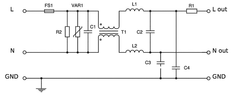
Figure 1. In this typical EMI filter, the bleed resistor R2 draws a continuous current as long as the device is plugged in. Image used courtesy of Bodo’s Power Systems [PDF]
This circuit configuration makes it almost impossible to comply with the new standby power consumption regulation: the 377 mW dissipation continues all the time the device is plugged into a mains power socket, whether it is active, quiescent, or switched off.
Fortunately, adding a simple integrated circuit to stop power consumption through the bleed resistors is easy, except when the X-capacitors need to be discharged. Examples include the CAPZero-2 or CAPZero-3 from Power Integrations, the HF81 from Monolithic Power Systems, and the TEA1708T from NXP Semiconductors.
These parts all have a similar design. They consist of MOSFETs with integrated drivers, voltage sensing, and other circuits. They are placed in series with the bleed resistors. During normal operation (when an AC voltage is present), the MOSFETs are off, so the resistors are disconnected, and no current flows through them. When the device is unplugged and the AC voltage is removed, the MOSFETs turn on to bring the resistors into the circuit, discharging the X-capacitors.
The solution shown in Figure 2 provides a way to reduce the power wasted through the bleed resistors. It can be implemented as a cheap and easy modification of an existing power supply design, with minimal change to the bill-of-materials or board layout.
However, OEMs can choose from a new generation of power controllers that include an integrated X-capacitor discharge circuit for new designs. Examples are:
- HR1275 from Monolithic Power Systems, a combination controller with multi-mode PFC and LLC power stages
- TEA2017 from NXP, a combination controller with multi-mode PFC and LLC power stages
- NCP1618 from onsemi, a multi-mode PFC controller
- HiperPFS-5 from Power Integrations, a quasi-resonant PFC controller with integrated gallium nitride (GaN) FET
- L4985 from STMicroelectronics, a PFC controller that operates in continuous conduction mode.
These suppliers are innovating their product designs to save even more power in standby mode. For instance, many work in burst mode when the load is below a certain threshold, allowing the power supply control and switching circuits to be intermittently disabled.
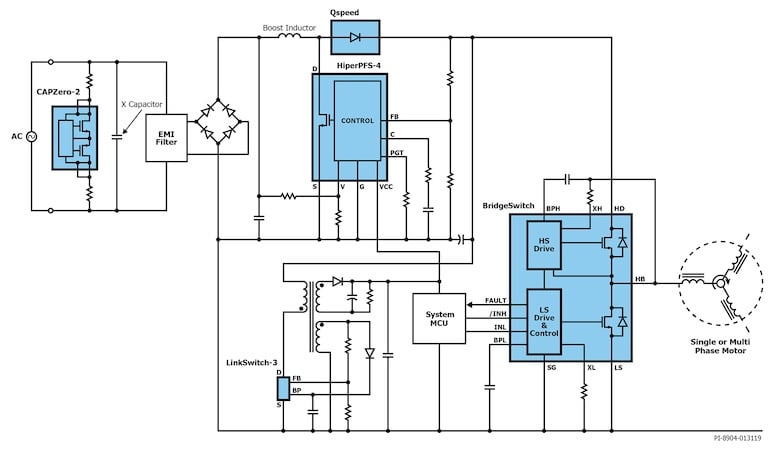
Figure 2. A typical high-voltage motor control board shows the CAPZero-2 X-capacitor discharge circuit. (Image credit: Power Integrations).
Tests performed by Monolithic Power Systems reveal the huge power savings that can be made by using the HF81 in this way: the test results are published in the datasheet of the HF81 (see Figure 3). For our example above of an X-capacitor of 2.2 µF, the saving made using the HF81 would bring power dissipation through the bleed resistors to below 200 mW—low enough to allow compliance with the 2023/826 regulation. Power Integrations and NXP separately specify the power dissipation of their ICs at less than 5 mW.
|
X-capacitance |
Total Series Resistance |
Power Saving at an Input Voltage of 265 V ac |
|
<500 nF |
1.5 MΩ |
- |
|
750 nF |
1 MΩ |
66 mW |
|
1 μF |
780 kΩ |
86 mW |
|
1.5 μF |
480 kΩ |
142 mW |
|
2 μF |
360 kΩ |
191 mW |
|
2.5 μF |
300 kΩ |
230 mW |
|
3.5 μF |
200 kΩ |
347 mW |
|
5 μF |
150 kΩ |
464 mW |
Figure 3. Power savings are made by replacing a conventional X-capacitor discharge circuit with one based on the HF81 from Monolithic Power Systems.
The scale of the improvements that can be made is substantial: with its TEA2017, NXP has reduced low-load and quiescent mode power consumption compared to its predecessor, the TEA2016 (see Figure 4).
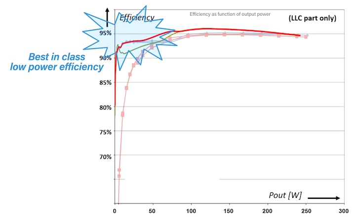
Figure 4. Efficiency graph showing the reduced power losses at low load in the latest TEA2017 power controller from NXP (red curve) compared to the TEA2016 (pink curve). (Image credit: NXP Semiconductors)
Implemented in an NXP evaluation board, the TEA2017DK1003, a 600 W offline AC-DC converter with a 12 V output, the TEA2017 enables the power supply to reduce no-load power consumption to 0.11 W with a 230 V AC input. The TEA2017 also provides the main power control functions in the new Lightning AC-DC converter board developed by Future Electronics’ European Power Centre of Excellence. Technical information about the Lightning board, which provides a 42 V DC output and supports loads of up to 240 W, can be found at www.my-boardclub.com, where engineers can apply to receive the board.
Power Integrations, onsemi, and ST also supply evaluation boards that demonstrate the capability of controllers with integrated X-capacitor discharge to support compliance with regulation 2023/826
Power Integrations provides the DER-672, a 220 W evaluation board that achieves no-load power consumption of 120 mW at 230 V ac thanks to its PFS5178F, a quasi-resonant PFC controller with GaN FET, operating in discontinuous conduction mode.
From onsemi comes the NCP13994MM360WGEVB, a 360 W evaluation board in which the NCP1618 multi-mode PFC controller is used with the NCP13994, the latest current-mode LLC controller. At 230 V AC, the no-load power consumption of the NCP13994MM360WGEVB is 100 mW.
ST, on the other hand, supplies a 400 W evaluation board, the EVL400W-80PL, in which the L4985A PFC controller operating in continuous conduction mode achieves no-load power of less than 150 mW at 230 V AC.
Power Semiconductor Market Response to Lower Standby Power Demand
The TEA2017 and the other new and improved products featured in this article show that the component market is ready to provide various solutions to power-supply designers who must comply with the tight restrictions on standby and off-mode power consumption specified in the EU’s latest regulation.
This article originally appeared in Bodo’s Power Systems [PDF] magazine.