 Facebook
 Google
 GitHub
 Linkedin
DC-AC Power Electronics Converters for Battery Energy Storage
Power electronics-based converters are used to connect battery energy storage systems to the AC distribution grid. Learn the different types of converters used.
The power conditioning system (PCS) only makes up a small portion of the overall costs for lithium-ion and lead-acid battery-based storage systems, as shown in Figure 1. However, the PCS's share of costs will increase due to the falling prices of battery cells, as shown in Figure 2. In this light, it is wise to design the power electronics converter for maximum efficiency and dependability, thereby lowering the total cost of ownership.

Figure 1. Absolute and Relative Costs for Different Electrochemical Technologies. Image used courtesy of IEEE Open Journal of the Industrial Electronics Society

Figure 2. Lithium-ion battery cell and pack costs over the last ten years. Image used courtesy of IEEE Open Journal of the Industrial Electronics Society
Designing an Inverter
Battery peculiarities must be considered when designing an inverter. Between fully charged and fully discharged states, the terminal voltage of the cells can vary by up to 40%.
Additionally, the AC voltage should be maintained as high as possible to minimize current stress in the semiconductors, which is the primary source of loss in the power electronics converter. By such means, it is guaranteed to have a highly efficient DC-AC conversion.
The international norms fix the border between low and medium voltage (MV) at 1.5 kV, with additional safety requirements for appliances working at MV. At the same time, efficiency maximization will push for increasing the rated AC and DC voltages. Additionally, many battery cells connected in series may decrease system reliability. Also, consider the restrictions and requirements for safety, harmonic content, and P-Q capabilities established by technical standards and national grid codes.
Power Electronics Converters
Power electronics converters can first be categorized according to whether or not a step-up transformer is used. When transformers are not used, the voltage step-up required for the connection at MV can still be accomplished by connecting semiconductors or sub-modules in series. Additionally, the DC voltage can be managed by adding an additional DC-DC converter between the battery and the DC-AC converter connected to the grid. However, the additional conversion step increases complexity, raises costs, and may result in further power losses. Technical or operational difficulties must be cited as the reason for this decision. The most popular option for connecting stationary energy storage to the MV grid is a two-level (2L) voltage source converter (VSC), as shown in Figure 3(a). However, some other topologies have been created, including the three-level T-type, neutral point clamped (NPC) converter, and active neutral point clamped (ANPC) converter, which is each depicted in Figures 3(b), 3(c), and 3(d) respectively.

Figure 3. Transformer-based two-level and three-level DC-AC converter topologies: (a) two-level VSC, (b) three-level T-type VSC, (c) three-level neutral point clamped VSC, and (d) three-level active neutral point clamped VSC. Image used courtesy of IEEE Open Journal of the Industrial Electronics Society
Figure 4 illustrates the efficiency of the semiconductor module for 100 kW two-level and three-level VSCs connected to a 400 V line-to-line AC grid at various switching frequencies (fs). Table 1 lists the specifications for the converter. IGBT-Diode modules that are rated appropriately are picked for the analysis.

Figure 4. Efficiency at a rated power of PWM modulated two-level and three-level VSC topologies operating at different switching frequencies for the converter specifications given in Table 1. Image used courtesy of IEEE Open Journal of the Industrial Electronics Society
Table 1. Specifications considered for the efficiency and loss distribution comparisons between circuit topologies.
|
Parameter |
Pn |
UDC,n |
Uac,ll |
cos φ |
fs |
|
Value |
100 kW |
900 V |
400 V |
1 |
3-16 kHz |
At higher switching frequencies, three-level topologies perform better than two-level converters; additionally, neutral point clamped topologies, in particular, exhibit a better distribution of losses among the components, as shown in Figure 5. Higher switching frequencies also benefit from a shift away from human audible noise frequencies and a reduction in the volume of the AC output harmonic filter, which increases converter power density. Large grid-connected BESS are housed in containers and are typically installed away from people, which enables the power electronics to run at low switching frequencies, like 4 kHz, well within the audible noise range for humans. Low switching loss across the semiconductors, as shown in Figure 5 in red, is the result of this. Additionally, as shown in Figure 5, two-level VSC exhibits exceptional conduction losses, which justifies its widespread use at those low fs levels.

Figure 5. Losses distribution in two-level (a) and three-level (b)-(c)-(d) topologies during inverter operation, with switching frequency fs = 4 kHz (blue+red) and fs = 12 kHz (blue+red+yellow), considering the specifications in Table 1 and the components nomenclature of Figure 3. Image used courtesy of IEEE Open Journal of the Industrial Electronics Society
According to the cost comparison for energy storage MV converters, the modular multilevel converters (MMCs), shown in Figure 6, are more expensive than the cascaded H bridge (CHB), shown in Figure 7, which is a more affordable alternative. Multilevel topologies, like the CHB and MMC, have been demonstrated to be effective circuit topologies for grid-connected energy storage applications because they offer a low overall harmonic content, a high power density, and a high efficiency at high switching frequencies.

Figure 6. Three-phase DC-AC MMC. Image used courtesy of IEEE Open Journal of the Industrial Electronics Society

Figure 7. Three-phase DC-AC CHB. Image used courtesy of IEEE Open Journal of the Industrial Electronics Society
Dependability of Energy Storage Systems
Power electronics and battery cells are considered when examining the dependability of energy storage systems. Two BESS configurations, a fully rated 2 L converter, and four partially rated 2 L converters were all compared. The two configurations are tested under various operating conditions, battery power, cycle counts, and series-parallel cell configurations. The study demonstrated the potential for higher reliability in low-power applications. Furthermore, it was discovered that the relationships among reliability, power level, and cycles are inversely proportional. The study results can be used as a guide for future reliability studies and comparisons of various topologies and battery cell configurations.
According to the literature reviewed, even though the two-level VSC topology is the most popular for grid-connected BESS converters, other topologies can ensure superior cost, efficiency, power density, and system reliability. Additionally, it has been established that battery functionality, followed by operating conditions, affects the effectiveness and dependability of converters. Despite this, few studies demonstrate how switching to a more efficient converter affects the cost of ownership for BESS. In light of this and the knowledge provided by Figures 4 and 5, further research should concentrate on demonstrating the effects of various converter topologies on BESS's technical and financial performance. Additionally, it is crucial to conduct this analysis for various grid functionalities, demonstrating how the various operational requirements affect the DC-AC converter designs and performances.
Key Takeaways of DC-AC Power Electronics Converters for BESS
This article has discussed the various BESS power electronics converters. Some of the takeaways follow.
- The power electronics converter should be designed for maximum efficiency and dependability to reduce the total cost of ownership.
- To ensure a highly efficient DC-AC conversion, the rated AC voltage should be kept as high as possible to reduce current stress in the semiconductors, which is the main cause of loss in the power electronics converter.
- A two-level (2L) VSC, a three-level T-type NPC converter, or an ANPC converter is the most widely used option.
- Three-level topologies outperform two-level converters at higher switching frequencies; additionally, neutral point clamped topologies, in particular, show a better distribution of losses among the components.
- The MMCs offer very low harmonics content for grid-connected applications, but they are more expensive than the CHB.
- Although the two-level VSC topology is the most common for grid-connected BESS converters, other topologies can provide superior performance in terms of cost, efficiency, power density, and system reliability.
This post is based on an IEEE Open Journal of the Industrial Electronics Society research article.
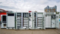
Featured image used courtesy of Adobe Stock


Very nice overview. One note on switching frequency, as any beneficial gain in engineering must be met with a con, increasing the switching frequency can certainly lead to higher efficiency, but can be met with increased EMI due to the higher dV/dt. This also holds for increasing the voltage magnitudes. On one hand less copper losses, on the other an increase in dV/dt. Especially for high-density, 2-level systems, it is often a compromise that must be met between efficiency and EMC.