 Facebook
 Google
 GitHub
 Linkedin
Utilizing Totem-Pole Bridgeless PFCs
This article highlights ICERGi low-cost control and drive ICs simplifying totem-pole bridgeless PFC designs.
The current industry focus has been on deploying either wide band gap (WBG) or low voltage Silicon switches to enable 99% efficiency in totem-pole bridgeless PFC. However, the wide adoption of the totem-pole bridgeless solution for multiple markets and applications would require more than just the readiness of power components. The topic that is often overlooked in recent literature is the need for low-cost control and isolated drive solutions.
WBG Switch + Totem Pole PFC = Highest Efficiency In offline switched mode AC/DC power supplies, active power factor correction (PFC) is generally required for input power exceeding 75W, as mandated by IEC 61000-3-2 [1]. This function has been historically achieved by a low-cost diode full-bridge rectification and a singleswitch boost converter at the expense of low efficiency and bulky designs.
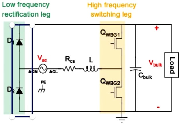
Figure 1: Totem-pole bridgeless PFC Design using WBG switches
The totem pole bridgeless topology as shown in Figure 1 is becoming more popular recently due to its highest efficiency and low component counts. Minimal conduction loss is achieved by: •
- Replacing a diode full-bridge rectification with a half-bridge rectification,
- Using only active devices for the high frequency boost leg,
- Enhancing the rectification leg with active devices, e.g. Super Junction (SJ) MOSFETs.
The totem-pole bridgeless PFC faces several practical challenges due to the hard switching of the boost leg. Using standard SJ 600V MOSFETs is impractical because the reverse recovery losses would be too high. This leads to the exploration of Wide-Bandgap (WBG) devices, e.g. GaN, SiC [2]. However, for designers, these WBG devices are currently not standardized making a second source challenging and are high cost.
What is often overlooked is the impact on the magnetic components of using WBG devices. The hard-switching loss generally confines the operating frequency of WBG devices to < 100kHz, which results in a high volt-seconds product being applied across the inductor. This means that a WBG-based totem-pole PFC design does not provide any benefit of magnetics size reduction as compared to the conventional boost PFC.
Another understated challenge for the totem-pole PFC is the cost for controllers and gate drivers. Unlike the conventional PFC, the inductor current cannot be simply measured by a low-side current sense resistor in the totem-pole circuit. A common fix is to use a high-side current sense resistor in series with the main inductor. However, this will make the current sense signal floating, and as a result the whole control circuitry must be designed with either isolated gate drivers or operational amplifiers or both, which has a significant impact on the system cost.
Silicon Switch + Totem-pole PFC = Highest Efficiency + 75% Smaller Inductor
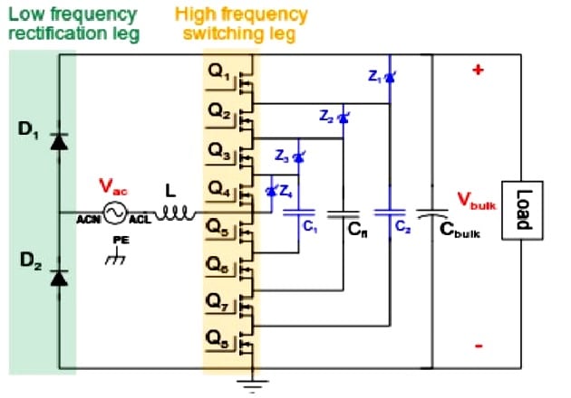
Figure 2: Totem-pole Bridgeless PFC Design using MOSFET switches
Reverser recovery losses are not an issue for low voltage (<150V) MOSFET devices thanks to advanced silicon technologies. This feature enables a Silicon based design for the totem-pole bridgeless PFC. Figure 2 shows a cost and performance-optimized solution developed by ICERGi, in which 8 x 150V MOSFETs are arranged to achieve a similar voltage rating as 600V SJ MOSFETs. Three flying capacitors C1, C2, and Cfl are added to the circuit for both active and passive voltage sharing control. In particular, the voltage across Cfl will be actively controlled to follow the reference of 2*Vbulk/4 using an enhanced phase-shift modulation (ePSM) scheme. The voltages across C1 and C2 are passively clamped to follow the references of 3*Vbulk/4 and Vbulk/4, respectively using Zener-type devices Z1, Z2, Z3, and Z4.
The switching leg is controlled to allow zero power flowing through C1 and C2 at all time during operation. Therefore, those capacitors and associated clamping devices as highlighted in BLUE do not have to handle any power, minimizing impact on cost and design complexity.
The ePSM scheme and flying capacitor arrangement enable half of the voltage applying to the PFC inductor for half of the time. This innovation enables a 4 x reduction in volt-seconds product, which can be translated into:
- A 4 x smaller PFC inductor and smaller EMI filters
- Inherently lower dV/dt and dI/dt which is of value in limiting EMI/ EMC effects.
- Improved low-line efficiency by having a smaller inductor
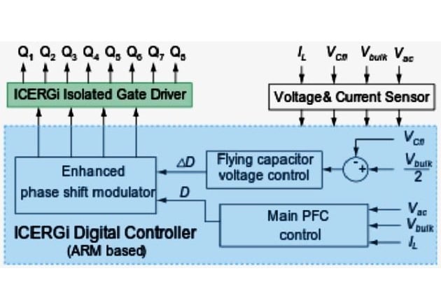
(a) Block diagram of ICERGi digital control & drive solution
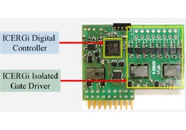
(b) Hardware implementation
Figure 3: Integrated drive and control card developed for the Siliconbased totem-pole PFC design
Even though the use of MOSFET switches and digital modulation helps to greatly reduce the power stage BOM cost and inductor volume, the control and multiple isolated drive still need to be addressed to make the totem-pole bridgeless PFC suitable for a wide range of applications.
Low-cost Control and Isolated Drive — Key Enabler
Having low-cost control and isolated drive is important to push for a wider adoption of totem-pole bridgeless PFC. This has been ICERGi’s strategy from day one. We developed a digital control solution based on low-cost low-resource ARM Cortex silicon. The control IC facilitates a smart sampling feature simplifying inductor current measurement. A control and drive solution with ePSM is illustrated in Figure 3(a).
The ICERGi drive technology enables the driving of multiple switching devices with low component counts at low cost by obviating the need for local power supplies as typically required by commercial isolated driver ICs. This self-powering feature enables compact implementation of the proposed drive and control architecture. In particular, the ARM Cortex M0-based digital controller and 8 isolated drivers can be easily housed in a compact low-cost daughter board as demonstrated by Figure 3(b). Here, the driver technology provides 8 isolated drive channels in 625mm2 (78mm2/channel) of board space. The magnetic elements are planar E-cores. Since the energy to switch is derived from the drive signal, the need for a bias supply is removed leading to significant design simplification.
Titanium PFC at Low Cost — New Normal
ICERGi’s low-cost PFC control and drive ICs enable the inherent advantages of totem-pole bridgeless PFC to be realised in a practical and cost-effective fashion at power levels from 600W to 3.3kW for single-phase AC/DC markets. Figure 4 shows a front-end 2.4kW PFC stage which is designed using ICERGi’s control and drive ICs. The boost leg is implemented by standard 150V 16mR MOSFETs and 5.4uF flying capacitors. The compactness of the PFC inductor not only reduces the system cost but also enhances low-line efficiency.
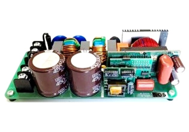
Figure 4: 2.4kW PFC reference design using a totem-pole bridgeless topology and 150V MOSFET switches
Figure 5 presents the PFC stage efficiency measured at both high line and low line with a 100W step load. The stage efficiency peaks around 98.8% at 230Vac and 97.5% at 115Vac. The peak efficiency at 230Vac can be lifted to 99% by replacing the diode rectification with active devices. The efficiency curve is relatively flat and shows modest roll-off at full power.
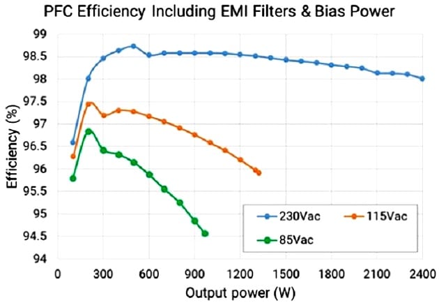
Figure 5: Efficiency of the 2.4kW PFC prototype
Summary
ICERGi offers low-cost control and drive ICs simplifying totem-pole bridgeless PFC designs, allowing the inherent high efficiency advantages to be realised in a practical and cost-effective fashion for single phase applications.
The 99% efficiency can be achieved by totem-pole bridgeless topologies using either standard proven Silicon MOSFETs or WBG devices. In both scenarios, ICERGi’s control and drive solutions can simplify design complexity and reduce system cost. The Silicon-based design have sustainable competitive advantage in magnetics size, EMI noise, and an expected long-term cost advantage over WBG -based solutions through second sourcing opportunities of switches, and smaller magnetics.
References
[1] Limits for Harmonic Current Emissions (Equipment Input Current < 16A per Phase), IEC Std. 61000-3-2
[2] L. Zhou, Y. Wu, J. Honea, and Z. Wang, “High-efficiency true bridgeless totem pole PFC based on GaN HEMT: Design challenges and cost-effective solution”, in Proc. Power Conversion Intelligent Motion Conf., May 2015, pp. 1482-1489
[3] T. T. Vu and E. Mickus, "99% Efficiency 3-Level Bridgeless Totempole PFC Implementation with Low-voltage Silicon at Low Cost," IEEE Applied Power Electron. Conf. and Expo. (APEC), Mar. 2019, pp. 2077-2083
About the Author
Trong Tue Vu holds a Ph.D. in Electronics Engineering at Maynooth University, a Master's Degree in Electrical, Electronics and Communications Engineering at Dublin City University, and a Bachelor's Degree in Electrical, Electronics and Communications Engineering at Ho Chi Minh City University of Technology. Trong Tue Vu is currently the CEO of ICERGi Ltd. since January 2018.


Hi Trong Tue Vu, I may need to know some more technical details, could we talk together?
Tuấn Đặng - was in HCMUT.