Making Sense of the Fundamentals and Configurations of 3-Phase Transformers
This article teaches three-phase transformers' fundamental principles and configurations, including their construction with three primary and three secondary windings. It also highlights the necessity of matching voltage ratings for proper integration into a three-phase system.
Three-phase transformers comprise three primary and three secondary windings, enabling the alteration of three-phase voltages analogous to single-phase transformers for single-phase voltages.

Image used courtesy of Adobe Stock
The article examines the complexities of transformer connections in delta and wye configurations and explains the relationship between turns ratio and voltage ratio. It emphasizes the critical role of matching voltage ratings in establishing appropriate transformer connections within a three-phase system. Additionally, the article touches on power calculations, highlighting the fundamental principle that power input must equal power output in a transformer.
Three-Phase Transformers
Three-phase transformers change values of three-phase voltages like single-phase transformers change values of single-phase voltages. Just as three-phase alternators require three coils to generate three-phase power, a three-phase transformer has only three primary and three secondary windings. The symbol is shown in Figures 1 and 2.

Figure 1. Three-phase transformer symbol for a one-line diagram. Image used courtesy of Ahmed Sheikh

Figure 2. Symbols for three-phase transformers. Image used courtesy of Ahmed Sheikh
Utility companies often use three single-phase transformers to create a three-phase transformer bank. The single-phase transformers are said to be banked to form a three-phase transformer bank. Other types of three-phase transformers are manufactured as a single unit with three primary and three secondary windings in a single enclosure wound on a common core. We will first examine how three single-phase transformers connect to form a three-phase transformer bank. All the rules will also apply to the three primary and secondary windings of a three-phase transformer, which is manufactured as a single unit.
Each transformer's primary winding acts as one phase of a three-phase load supplied by the three-phase line voltage. Each transformer secondary winding is one phase of a three-phase supply voltage that supplies three-phase power to a three-phase load, often at a different voltage than the primary line voltage. The three single-phase transformer windings can be connected in either delta or wye—the same way as the phase coils of an alternator or any three-phase load.
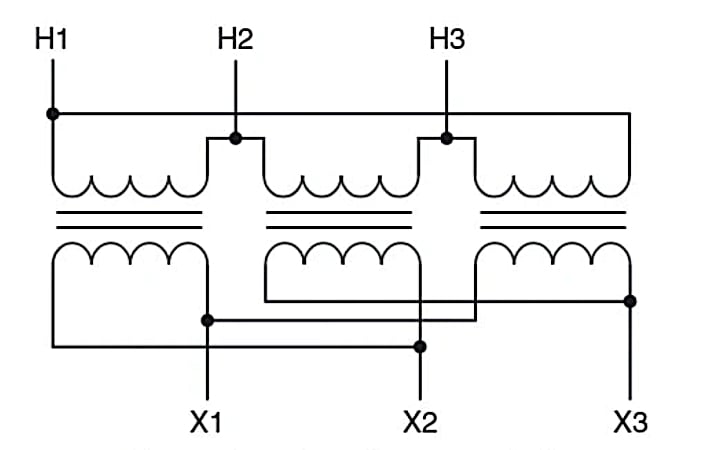
There is, however, the added complexity that transformers have two windings—H and X—and each may be connected in a wye or a delta independent of the other, as shown in Figure 3. As a result, the rule that the transformer turns ratio equals the transformer voltage ratio does not apply in the same way with three-phase transformers. The following figure demonstrates this fact.

A. Delta-connected H coils and X coils with a 2 to 1 turn ratio

B. Delta-connected H coils and wye-connected X coils with a 2 to 1 turns ratio
Figure 3 (A and B). Three single-phase transformer connections illustrate that the turns ratio does not always equal the voltage ratio with three-phase transformers. Image used courtesy of Ahmed Sheikh
Winding Turns Ratio and Line Voltage Ratio
Suppose we have three single-phase transformers that each has a 2 to 1 turns ratio, and we apply a single-phase voltage of 100 V to the H winding of one transformer. In that case, the voltage induced in the X winding of that transformer will be 50 V. Connecting the three transformer H windings in a delta configuration, as shown in Figure 3A, means connecting the start of each winding to the end of the other (the H1 of one transformer to the H2 of another). When connected to a three-phase line voltage of 100 V, the voltage across each transformer H winding is the same as the three-phase line voltage, and as a result, the voltage across each of the X windings will be 50 V because the turns ratio is 2 to 1. The three X windings can be connected in either a delta or a wye configuration; in either configuration, the phase voltage will be 50 V. If the X windings are connected in a delta—X1 to X2—as shown in Figure 3A, the induced voltage will result in a three-phase line voltage of 50 V because, in a delta connection, the coil phase voltage is the same as the three-phase line voltage. In this case, the turns ratio—2 to 1—is the same as the voltage ratio for the primary to secondary line voltage—100 V to 50 V.
Connecting the X windings in a wye configuration with all the X2 terminals together, as shown in Figure 3B, results in 86.5 V (50 V x 1.73 = 86.5 V) between any two of the X1 terminals; this is the line voltage of the wye system. The ratio of turns of the phase windings—2 to 1—is not the same as that of primary to secondary line voltage, which is 100 V to 86.5 V, or 1.15 to 1.
Single-Phase Transformer Voltage and 3-Phase Line Voltage
Just as the voltage applied to a single-phase transformer cannot exceed the windings' rating, the three-phase system's phase voltage cannot exceed the voltage rating of the single-phase transformers used to create the three-phase transformer. A 480-V three-phase system can be connected to three single-phase transformers with voltage ratings of 277 V if the transformers are connected in a wye configuration.
The same three single-phase transformers, however, cannot be connected to a 480 V three-phase system connected in a delta configuration because the phase voltage of the delta system is the same as the line voltage of 480 V. That voltage exceeds the 277-V rating of the single-phase transformers.
The general rule is that the voltage rating of the single-phase transformers must be the same as the three-phase line voltage if they are to be connected in a delta system. If the single-phase transformer voltage rating is less than the three-phase line voltage, they must be connected in a wye configuration.
Three-Phase Transformer Power
While the transformer winding connections may change the rule about transformer turn ratios, no matter what type of three-phase transformer connection is used, the basic rule that the power into the transformer must equal the power out of the transformer is still true.
If the primary line voltage is 480 V and the load draws 25 amps, the three-phase power is:
\[\frac{1.73\times480V\times25\,A}{1000}=20.7\,kVA\]
If the secondary line voltage is 208 V, the secondary line amps must equal:
\[\frac{20.7\,kVA}{1.73\times208\,V}=57.6\,A\]
Remember, the three-phase transformer power rating is the sum of the three single-phase transformer power ratings used to create it.
Three-Phase Transformer Principles Conclusion
A thorough understanding of transformer construction, winding configurations, turns ratio, and voltage ratings is crucial for efficient power distribution and effective management of three-phase systems. Knowledge of properly connecting transformers in either delta or wye configurations ensures electrical networks' safe and optimal operation. Moreover, calculating power accurately and adhering to the fundamental principle of power equivalence in transformers is essential for maintaining a reliable and balanced power supply. Ultimately, this in-depth understanding enables engineers to design, implement, and maintain robust electrical systems, contributing to the seamless functioning of modern power grids and industries.


