Facebook
 Google
 GitHub
 Linkedin
Control Transformer Operation and Sizing
There are several special types of transformers that are similar to the more common types of transformers but have special features for particular applications. Control transformers are used to provide low-voltage power to control systems and devices.
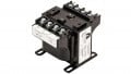
Control Transformers
A control transformer is a transformer that is used to step down the voltage to power the control devices of a circuit or machine. The reduced voltage provides a much safer environment for technicians working on the equipment. Residential heating, ventilating, air conditioning systems, and other machines use reduced voltage for the controls, thermostats, relays, and contactors. Control transformers are often referred to as power supplies.
Operation of Control Transformers
Control transformers with two primary coils and one secondary coil are the most common. A control transformer's primary coils are crossed so that metal links can be used to connect the primaries for 240 V or 480 V operation (see Figure 1).
Many control transformers are designed to provide 12V or 24V power from the secondary. However, some control transformers provide 120V power. For example, a control transformer with a 10:1 turns ratio can have the two primary coils wired in parallel. This steps down the primary voltage from 240V to 24V on the secondary. When the control transformer's two primary coils are wired in series, the voltage is stepped down from 480V to 24V.

Figure 1. In order to deliver 24V, the control transformer primary coils can be connected in parallel for a 240V source or in series for a 480V source.
Some plants have a 600V system that requires the control transformer primary windings to be rated for 600V. This type of transformer typically has a dual-voltage secondary, which makes this unit highly versatile (see Figure 2). This type of transformer typically delivers 120V or 240V power from the 600V source. Control transformer sizes typically range from 50VA to 3kVA.

Figure 2. For a 600V source, the secondary coils can be connected in parallel for a 120V secondary or in series for a 240V secondary.
Understanding Control Transformer Sizing
There are three characteristics of a circuit that must be determined before selecting a control transformer. The three characteristics are sealed VA, inrush VA, and inrush load power factor. The sealed VA is the power, in VA, that the transformer must deliver to the load for an extended period of time. The inrush VA is the power, in VA, that the transformer must deliver to the load upon startup. The inrush VA can often be 10 times the sealed VA. The inrush load power factor is the power factor of the inrush current. The inrush load power factor is difficult to determine, but 40% is a reasonable estimate for most situations. Manufacturers provide tables to help in the selection.
The control transformer's size can be calculated by adding the power requirements of the components in the control circuit. For example, a heating, ventilating, and air conditioning (HVAC) building controller may require 10VA of 24V power. The controller also provides power to two humidity sensors and two electronic/pneumatic transducers. The two sensors and two transducers require 3VA each for a total of 12VA. Therefore, the control transformer must be sized to provide at least 22VA (10 + 12 = 22) of sealed VA.
Undersized Control Transformers
Processes often change over time, with the result that control systems are modified to match the changes. Additional relays and contactors may be installed without considering the size of the control transformer. If the control transformer is not replaced, it may be undersized for the new circuits. When the total load connected to a control transformer exceeds the rating of the transformer, the voltage output of the transformer decreases.
A circuit can be difficult to troubleshoot if the control transformer is undersized. A technician needs to understand how the other equipment in the circuit should operate. For instance, a relay, starter, or contactor has two power ratings. The lower rating is the hold-in VA rating. The higher rating is the pull-in VA rating.

Figure 3. A DMM set in MIN MAX recording mode can be used to identify a circuit with an overloaded control transformer.
The modified control system may have enough power to hold in an armature, but it may not have enough power to pull in the armature. Therefore, the relay, contactor, or starter cannot close and complete the circuit. However, if the armature is manually pushed in, the circuit will operate normally.
It can also be difficult to determine when a control transformer is undersized because most troubleshooting measurements are taken when all or almost all loads in a circuit are OFF. A digital multimeter set to record the minimum and maximum voltage can be used to detect a low-voltage condition caused by circuit overloading (see Figure 3).