Facebook
 Google
 GitHub
 Linkedin
Cascaded and Hybrid Concepts for Voltage Conversion
This article features Analog Devices, Inc. voltage conversion devices with LTM8027 and LTM4624 μModule regulators, and LTC7821 hybrid step-down controller. /></body></html>
There are different solutions for applications that require conversion from a high input voltage down to a very low output voltage. One interesting example is the conversion from 48 V down to 3.3 V. Such a specification is not only common in server applications for the information technology market, but in telecommunications as well.
If a step-down converter (buck) is used for this single conversion step, as shown in Figure 1, the problem of small duty cycles emerges.

Figure 1: Conversion of a voltage from 48 V down to 3.3 V in one single conversion step.
The duty cycle is the relationship between the ON-time (when the main switch is turned ON) and the OFF-time (when the main switch is turned OFF). A buck converter has a duty cycle, which is defined by the following formula:
$$Duty \ Cycle = \frac{Output \ Voltage}{Input \ Voltage}$$
This means that at a switching frequency of 1 MHz (1000 ns per switching period), the Q1 switch is turned on for only 70 ns. Then, the Q1 switch is turned OFF for 930 ns and Q2 is turned on. For such a circuit, a switching regulator has to be chosen that allows for a minimum ON-time of 70 ns or less. If such a component is selected, there is another challenge. Usually the very high power conversion efficiency of a buck regulator is reduced when operating at very short duty cycles. This is because there is only a very short time available to store energy in the inductor. The inductor needs to provide power for a long period during the OFF-time. This typically leads to very high peak currents in the circuit. To lower these currents, the inductance of L1 needs to be relatively large. This is due to the fact that during the ON-time, a large voltage difference is applied across L1 in Figure 1.
In the example, we see about 44.7 V across the inductor during the ON-time, 48 V on the switch-node side, and 3.3 V on the output side. The inductor current is calculated by the following formula:
$$i_L = \frac{1}{L} \int u_Ldt$$
If there is a high voltage across the inductor, the current rises during a fixed time period and at a fixed inductance. To reduce inductor peak currents, a higher inductance value needs to be selected. However, a higher value inductor adds to increased power losses. Under these voltage conditions, an efficient LTM8027 μModule® regulator from Analog Devices achieves power efficiency of only 80% at 4 A output current.
Today, a very common and more efficient circuit solution to increase the power efficiency is the generation of an intermediate voltage. A cascaded setup with two highly efficient step-down (buck) regulators is shown in Figure 2. In the first step, the voltage of 48 V is converted to 12 V. This voltage is then converted down to 3.3 V in a second conversion step. The LTM8027 μModule regulator has a total conversion efficiency of more than 92% when going from 48 V down to 12 V. The second conversion step from 12 V down to 3.3 V, performed with a LTM4624, has a conversion efficiency of 90%. This yields a total power conversion efficiency of 83%. This is 3% higher than the direct conversion in Figure 1.

Figure 2: Voltage conversion from 48 V down to 3.3 V in two steps, including a 12 V intermediate voltage.
This can be quite surprising since all the power on the 3.3 V output needed to run through two individual switching regulator circuits. The efficiency of the circuit in Figure 1 is lower due to the short duty cycle and the resulting high inductor peak currents.
When comparing single step-down architectures with intermediate bus architectures, there are many more aspects to consider besides power efficiency.
One other solution to this basic problem is the new LTC7821, hybrid step-down controller from Analog Devices. It combines charge pump action with a step-down buck regulation. This enables the duty cycle to be 2× VIN/VOUT and, thus, very high step down ratios can be achieved at very high power conversion efficiencies.
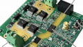
Figure 3 shows the circuit setup of the LTC7821. It is a hybrid step-down synchronous controller. It combines a charge pump to halve the input voltage with a synchronous step-down converter utilizing the buck topology. With it, conversion efficiencies of more than 97% for converting 48 V to 12 V at a 500 kHz switching frequency are possible. With other architectures, this high efficiency would only be feasible with much lower switching frequencies. They would require larger inductors.

Figure 3: Circuit design for a hybrid step-down converter.
Four external switching transistors are activated. During operation, the capacitors C1 and C2 generate the charge pump function. The voltage generated in this way is converted into a precisely regulated output voltage with the synchronous buck function. To optimize the EMC characteristics, the charge pump is used with soft switching operations.
The combination of a charge pump and a buck topology offers the following advantages. Due to the optimal combination of charge pump and synchronous switching regulator, the conversion efficiency is very high. The external MOSFETs M2, M3, and M4 only have to withstand low voltages. The circuit is also compact. The coil is smaller and cheaper than in a single-stage converter approach. For this hybrid controller, the duty cycle for switches M1 and M3 is D = 2 × VOUT/VIN. For M2 and M4, the duty cycle is calculated as D = (VIN – 2 × VOUT)/VIN.

Figure 4: Typical conversion efficiency for converting 48 V to 5 V at a switching frequency of 500 kHz.
For charge pumps, many developers assume a power output limitation of approximately 100 mW. The hybrid converter switch with the LTC7821 is designed for output currents of up to 25 A. For even higher performance, multiple LTC7821 controllers can be connected in a parallel multiphase configuration with synchronized frequency to share the overall load.
Figure 4 shows the typical conversion efficiency for a 48 V input voltage and a 5 V output voltage at different load currents. At approximately 6 A, a conversion efficiency exceeding 90% is reached. Between 13 A and 24 A, the efficiency is even higher than 94%.
A hybrid step-down controller supplies very high conversion efficiency in a compact form. It offers an interesting alternative to a discrete two-stage switching regulator design with intermediate bus voltage and to a single-stage converter that is forced to operate at a very low duty cycle. Some designers will prefer a cascaded architecture, others a hybrid architecture. With these two available options, every design should be successful.
About the Author
Frederik Dostal studied microelectronics at the University of Erlangen-Nuremberg, Germany. Starting work in the power management business in 2001, he has been active in various applications positions including four years in Phoenix, Arizona, working on switch mode power supplies. He joined Analog Devices in 2009 and works as a power management technical expert for Europe. He can be reached at [email protected]
This article originally appeared in the Bodo’s Power Systems magazine.