Facebook
 Google
 GitHub
 Linkedin
Silicon Carbide Inverter Solutions Enable Functionally Safe Drivetrain Design
Learn how SiC inverter solutions offer a modular, functionally safe platform with certified components, accelerating development and compliance with ISO 26262 for next-gen vehicles.
This article is published by EEPower as part of an exclusive digital content partnership with Bodo’s Power Systems.
Article is co-authored by Etienne Vanzieleghem, VP Engineering and Operations at CISSOID.
Due to growing concerns about climate change and energy efficiency, inverter-based electrification is transforming the automotive industry, as well as off-road vehicles and hydraulic machinery. Additionally, today’s vehicles are no longer regarded as merely machines of mobility; rather, they offer unprecedented functionality and user experiences ranging from improved fuel efficiency, reduced carbon emissions to sophisticated features like advanced driver assistance systems (ADAS) and smart infotainment. At the heart of this transformation lies a growing reliance on semiconductors, electronics, and software interfaces.
While modern vehicles continue to offer enhanced features and support climate and energy efficiency goals, their complexity due to the extensive integration of electronics and electrical (E/E) systems makes them more prone to failures and safety risks. If, due to any random failure, the vehicle does not perform its intended function, it might result in physical injury or damage. The goal of functional safety is therefore to make sure that the system is designed in such a way that, despite possible failure, damage can be prevented, or at least failure can be detected and controlled in a safe and predictive manner.
In recent years, there has been a lot of emphasis on functional safety implementation in vehicle applications, processes, and products. Accordingly, various industry standards have been defined for compliance. IEC 61508 is the generic functional safety standard for E/E systems. Notably, the following standards are in practice for various industries and applications,
- ISO 26262 deals with the functional safety of E/E systems in the automotive industry and on-road vehicles, including passenger cars, trucks, buses, and commercial vehicles.
- ISO 25119 deals with the E/E systems of tractors and machinery used in agriculture and forestry for off-road environments.
- ISO 19014 deals with the functional safety of E/E systems and mechanical/hydraulic systems for earth-moving machinery, trucks, bulldozers, excavators, loaders, and other mobile hydraulic actuators.
While each of these standards is critical within its specific domain, ISO 26262 remains the most comprehensive and mature framework for functional safety of E/E systems. Demonstrating compliance with ISO 26262 can significantly simplify alignment with other domain-specific standards, as it follows a common approach that includes hazard analysis, risk identification, and risk mitigation measures, as shown in Figure 1.
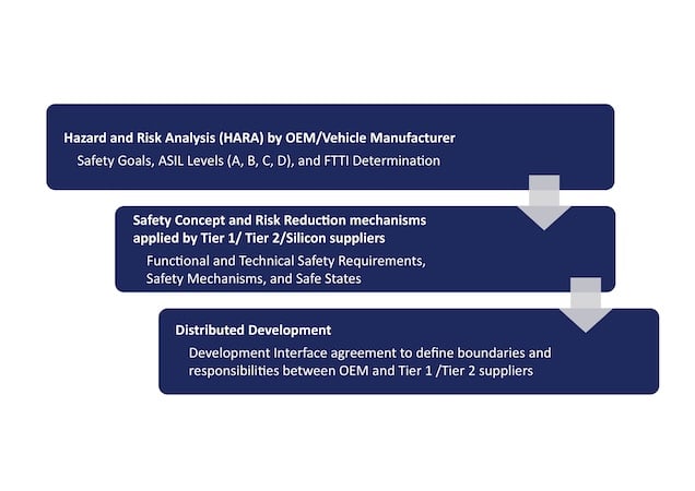
Figure 1. ISO26262 guidelines on Automotive Functional Safety. Image used courtesy of Bodo’s Power Systems [PDF]
Modern automobiles have numerous subsystems (e.g., antilock braking, electric steering, lighting control, etc.); however, powertrain and inverter subsystems are central to vehicle propulsion and control. Similarly, other vehicle platforms, including commercial trucks, off-road machinery, and marine vessels, heavily rely on inverters as a critical safety element within the powertrain.
The key aspects of the driving experience, including acceleration, braking, and overall manoeuvrability of the vehicle, depend on the precise and predictable operation of the powertrain. Any fault in the inverter can lead to sudden loss of power, loss of control, or unwanted acceleration, directly impacting the driver’s control over the vehicle and potentially resulting in accidents, especially at high speeds or in critical situations, such as overtaking, lane changing, or off-loading.
Therefore, inverters in drivetrains must be reliable and fault-tolerant to ensure the safety of the users and equipment in the vicinity of operation. Designing functionally safe inverters is therefore not just good engineering; it’s essential for the trust, reliability, and future of next-generation vehicles.
In line with this evolving market need, CISSOID offers a customizable, functionally safe inverter platform with a modular architecture and a complete product portfolio, including power modules, gate drivers, control boards, e-motor control software, and fully functional reference designs. Together, these elements provide a solid foundation for achieving functional safety in drivetrain inverter applications.
Understanding Functional Safety Requirements for a Powertrain Inverter
Functional safety of inverters is about proactively managing risks that stem from hardware or software failures in the inverter. The vehicle manufacturer performs a detailed hazard and risk analysis (HARA) based on which risks are identified, vehicle safety goals are defined, and Automotive Safety Integrity Levels (ASILs) are associated with each safety goal. ASIL A corresponds to the least strict requirements, while ASIL D corresponds to the most stringent, depending upon the criticality of the safety goal violation.
These goals generally include preventing unintended acceleration, braking, direction reversal, and thermal hazards under all operating conditions. Additionally, OEMs also define the fault-tolerant time intervals (FTTIs) for each safety goal within which a failure must be detected and the system must attain a safe state before the failure leads to a hazard.
These requirements on goals are passed down to Tier 1, Tier 2, and silicon suppliers, who are responsible for fulfilling these goals by implementing safety and risk mitigation measures. At the inverter manufacturer’s end, these goals are translated into Functional Safety Requirements (FSRs) and Technical Safety Requirements (TSRs) at the inverter level.
Accordingly, an inverter safety concept is derived on the principle of fault detection via safety mechanisms, and system reactions to put the inverter in a known safe state. The time intervals corresponding to fault detection and achieving a safe state are termed as Fault Detection Time Interval (FDTI) and Fault Reaction Time Interval (FRTI).
The complete time interval of detection and reaction is termed as Fault Handling Time Interval (FHTI) and must be lower than the OEM-specified FTTIs. For a three-phase power inverter, the safe state means stopping power flow from the source to the motor. This can be done by either turning OFF all SiC switches, called All Open Circuit (AOC), or turning ON all low- or high-side SiC switches, called Active Short Circuit (ASC), depending on the motor speed.
Due to all of these requirements and measures, achieving functional safety in modern vehicles is a complex process. It requires careful design of the safety concept, along with the implementation of fast, reliable, and configurable software and hardware safety mechanisms. This complexity can be substantially reduced by using certified hardware and software components.
The key challenges to attain functional safety include careful design choices, ultra-fast detection and reaction, early failure mitigation, and quick transition to a safe state. The combination of Silicon Mobility’s Adaptive Control App software with CISSOID’s Inverter Control Module (ICM) effectively addresses these challenges and offers a powerful solution for fast control, reliable diagnostics, and functional safety compliance.
Thanks to its modular and configurable structure with built-in safety features, it reduces the effort, time, and deep expertise needed to develop a functionally safe system. By using this solution, OEMs can already come one step closer to achieving functional safety certification with greater ease and confidence.
Modular solution enabling accelerated development and Functional Safety compliance
To enable the fast-track powertrain development and achieve functional safety compliance with minimum complexity, CISSOID offers a modular hardware solution catering to the needs of OEMs and powertrain developers at various levels. This includes a complete product range:
a) A 3-phase 1200V Silicon Carbide (SiC) MOSFET Intelligent Power Module (IPM) range that integrates high-performance power SiC switches and gate drivers, built on CISSOID’s HADES2® chipset. It is designed for high power density applications (340A– 550A), fully leveraging the benefits of SiC technology—namely, low switching losses and high thermal resilience. The SiC IPM offers safety mechanisms like desaturation detection (DESAT), undervoltage lockout (UVLO), active Miller clamping (AMC), soft shutdown (SSD), and anti-overlap control.
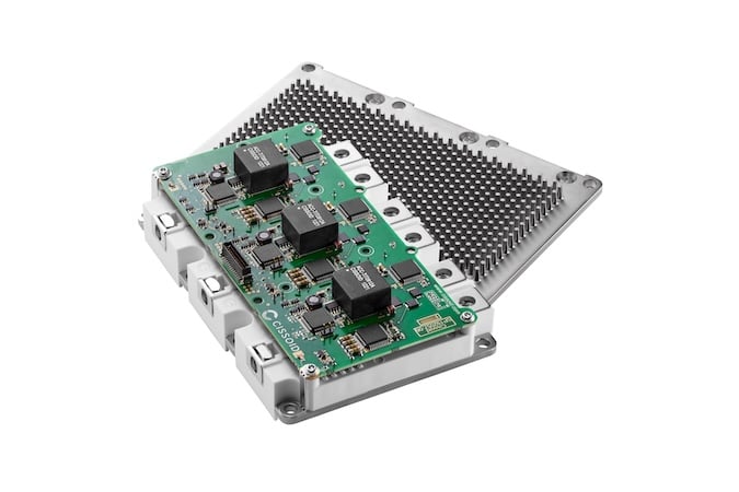
Figure 2. CISSOID’s Intelligent Power Module. Image used courtesy of Bodo’s Power Systems [PDF]
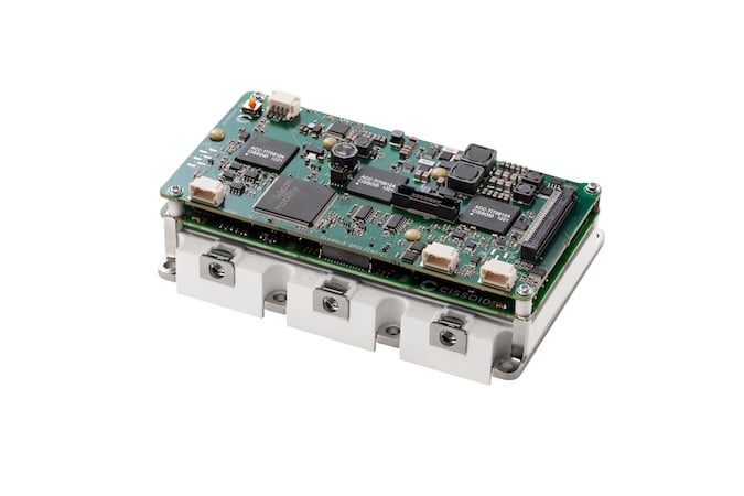
Figure 3. CISSOID’s SiC Inverter Control Module (ASIL-C Ready). Image used courtesy of Bodo’s Power Systems [PDF]
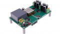
b) The ASIL-C Ready Inverter Control Module (ICM), integrating CISSOID’s IPM and a control board based on the ASIL-D certified Adaptive Control Unit (ACU)-T222 from Silicon Mobility, offering state-of-the-art performance and ultra-fast reaction times, along with all the necessary interfaces for automotive powertrain development.
The ICMs support Silicon Mobility’s ASIL-D certified Adaptive Control App inverter software, supporting Field Oriented Control (FOC) and advanced modulation including Space Vector Pulse Width Modulation (SVPWM) up to 50kHz, and Optimized Pulse Patterns (OPPs), along with I/O Safety Interfaces, as well as default and configurable fault detection and reaction safety mechanisms for powertrain functional safety, as shown in Figure 5.
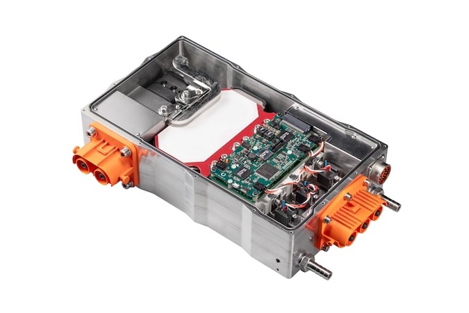
Figure 4. CISSOID’s SiC Inverter Reference Design. Image used courtesy of Bodo’s Power Systems [PDF]
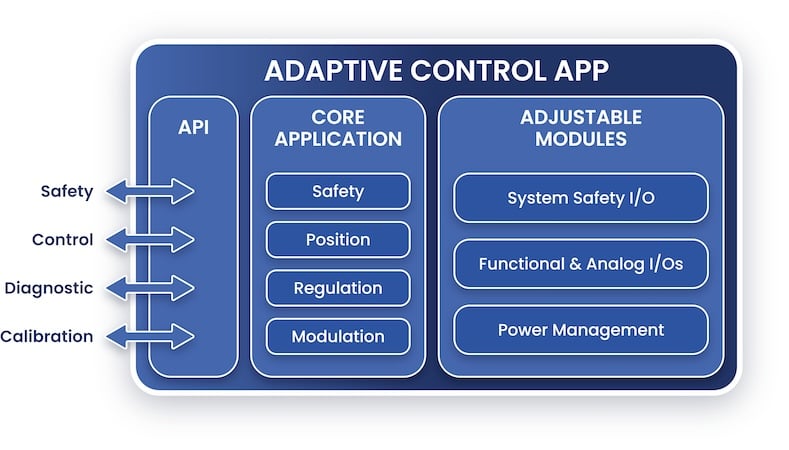
Figure 5. ASIL-D Certified Adaptive Control App -T222 Inverter software by Silicon Mobility. Image used courtesy of Bodo’s Power Systems [PDF]
c) CISSOID’s SiC Inverter Reference Designs (SIRDs), built up around an ICM, including a DC-link capacitor, EMI filter, and bleeder circuit (Figure 4) as a ready-to-use blueprint, helping OEMs and drivetrain makers to move quickly from concept to prototype without starting from scratch, with proven component integration and ease of functional safety compliance. The on-board SIRD is capable of supporting output power up to 463kWPEAK and DC Bus voltage up to 900VPEAK. With a broad voltage and power range, it provides a highly flexible and modular solution for new electric drivetrains that require operation in harsh environments, such as off-road and highperformance automotive, avionics, marine, and other demanding applications. For similar real-world conditions and cooling requirements, the SiC-based SIRD delivers more than 2x the output power compared to its counterpart IGBT-based design and maintains higher efficiency (>98%) across a broader speedtorque range. Unlike the IGBT Inverter, SiC-based SIRDs support higher torque at elevated speeds. These advantages make SiC ideal for demanding, high-performance electric drive applications. Using SIRDs, OEMs can quickly test, evaluate and assess the benefits of using SiC technology including higher efficiency, reduced switching losses, and improved reliability, along with the enablement of advanced software features, (e.g. optimized dead time compensation) for reducing total harmonic distortion (THD), losses and HVDC link voltage ripple.
The functional safety in the inverter subsystem is enabled by a central safety manager, which keeps track of Functional Requirements (FRs), Functional Safety Requirements (FSRs), and responds through the following Safety Mechanisms:
1. Ultra-fast digital comparators with configurable min/max thresholds to detect out-of-range (OoR) values of important safety parameters, e.g., phase currents, HVDC voltage, temperatures, etc. Thanks to the CISSOID control board sensing and filtering chain, and digital comparators on ADCs in the ACU-T222, any OoR anomaly can be detected in the order of 50 nanoseconds.
2. Analog comparators are available on the HADES2® chipset and ACU-T222 to detect overcurrent, undervoltage, and desaturation faults.
3. Thanks to the Adaptive Control App software, configurable software-defined safety mechanisms detect resolver faults, overspeed faults, over- and under-temperature, and over- and under-voltage for the HVDC battery. These can be detected within the order of a few milliseconds.
4. Safety digital input to respond to critical faults indicated by an external digital input or VCU, thanks to the ACU-T222, can be detected in the order of 50 nanoseconds. These safety mechanisms are user-configurable and redundant to ensure higher ASIL achievability. In case of failure, they enable fast detection and inform the safety manager to activate a safe state PWM (AOC or ASC).
Case Study—CISSOID SiC ICM Functional Safety compliance journey
For the functional safety compliance of the ICMs, CISSOID selected the most relevant vehicle safety goals, considering OEM customers’ needs and conducting extensive research on automotive industry requirements. The inverter is treated as a Safety Element Out of Context (SEooC) following ISO26262, where the vehicle-level safety requirements are provided by the integrator. These safety goals, their ASILs, and FTTIs are shown below.
|
ID |
Title |
FTTI |
Target ASIL |
Achieved ASIL |
|
SG1 |
Uncommanded accelerating torque shall be prevented - From an idle situation, no uncommanded start of movement. - From a running situation, no uncommanded acceleration. |
50 ms |
D |
D |
|
SG2 |
Uncommanded braking torque shall be prevented |
50 ms |
D |
C |
|
SG3 |
Unexpected reversal torque shall be prevented - From the idle position, if requested to accelerate in one direction, the vehicle should not go the other way. - While running, if requested to increase the speed, the vehicle should not decrease the speed & vice versa. |
50 ms |
D |
D |
|
SG4 |
Fire or thermal hazard shall be prevented |
100 ms |
C |
C |
|
SG5 |
Unintended loss of torque shall be prevented |
2000 ms |
QM |
C |
Table 1. Vehicle Safety Goals considered for ICM Functional Safety Readiness.
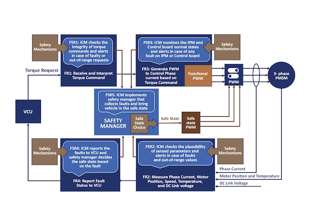
Figure 6. ICM Safety Concept in terms of FRs, FSRs, Safety Mechanisms, and Safe States. Image used courtesy of Bodo’s Power Systems [PDF]
A detailed failure mode, effects, and diagnostic analysis (FMEDA) for the ICMs is performed following ISO26262 guidelines and compiled in a configurable spreadsheet. Failure modes of ICM components are analysed according to standards (IEC 61709, IEC 62380), and ICM components’ basic FIT rates are calculated using SIEMENS’ standard SN29500. The relevant safety information from the ACU T222 and the Adaptive Control App T222 Inverter software by Silicon Mobility is included in the configurable FMEDA file. For the automotive mission profile specified by IEC62380, ICM safety metrics for a low speed case are given below in Table 2.
|
Safety (SG) |
Single Point (SPFM) [%] |
Latent Fault (LFM) [%] |
Probability (PHMF) [FIT*] |
Automotive (ASIL) |
|
SG 01 |
99.67 |
97.33 |
7.75 |
ASIL-D |
|
SG 02 |
99.24 |
87.71 |
20.22 |
ASIL-C |
|
SG 03 |
99.67 |
97.41 |
7.63 |
ASIL-D |
|
SG 04 |
99.46 |
88.97 |
15.17 |
ASIL-C |
|
SG 05 |
99.23 |
87.65 |
20.29 |
ASIL-C |
|
Overall ICM |
99.24 |
87.59 |
20.39 |
ASIL-C |
Table 2. ISO 26262 Hardware Architectural Safety Metrics for ICM * The Failures In Time (FIT) is the number of failures in one billion (109) device-hours of operation.
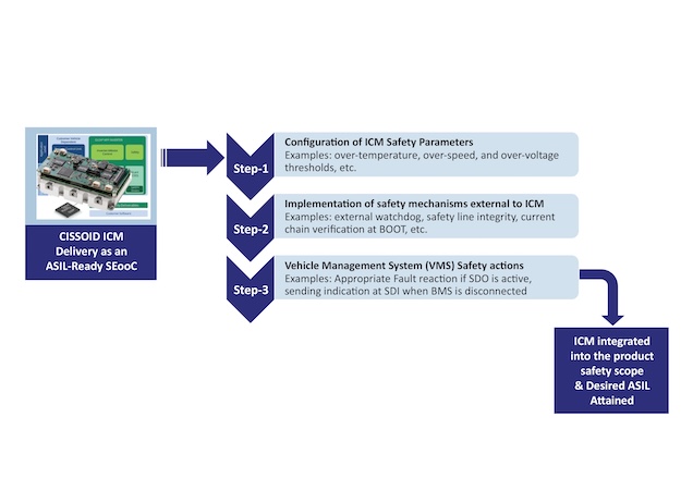
Figure 7. Main steps to integrate CISSOID’s ICM in the vehicle safety scope for Functional Safety compliance. Image used courtesy of Bodo’s Power Systems [PDF]
Development and Certification Support
For OEMs and vehicle manufacturers looking for advancements toward functional safety compliance, CISSOID offers a comprehensive ASIL-Ready Safety Package designed to streamline the safety compliance journey. This package empowers integrators with insights and tools to accelerate and simplify safety analysis for drivetrains and inverters. Following ISO26262 requirements, the safety package includes a configurable FMEDA spreadsheet and safety manual, along with the presentation of key safety features.
Automotive OEMs can use the configurable FMEDA Excel spreadsheet directly in their vehicle-level safety analysis based on their mission profile. This will significantly reduce the efforts for performing vehicle-level FMEDA. While OEMs in off-road, agricultural, construction, or hydraulic sectors must follow their domainspecific standards like ISO 19014, ISO 25119, and ISO 13849, the safety lifecycle defined in ISO 26262 provides a solid foundation and aligns well with these standards.
For these OEMs, the safety package will complement their vehicle-level safety analysis to meet the requirements of domain-specific standards, thereby fast-tracking the overall compliance process. The detailed working principles of various safety mechanisms, how to configure them, their FDTIs, information on safe states, their FRTIs, and overall FHTIs are also summarized in the dedicated safety manual and can be used by vehicle manufacturers for their vehicle-level safety analysis.
Backed by CISSOID’s proven expertise in high-temperature SiC applications, active co-engineering, tailored on-site support, and dedicated field application services, customers also gain access to high-level safety frameworks, resulting in fast-tracking the development as well as seamless integration and compliance with ISO 26262 standards. For the customers using the ICM product, the functional safety compliance includes the following steps, where dedicated guidance, documentation, and co-engineering support are available for each step.
|
Acronym |
Description |
|
AOC |
All open circuit |
|
ASC |
Active Short Circuit |
|
ASIL |
Automotive Safety Integrated Level |
|
FDTI |
Fault Detection Time Interval |
|
FHTI |
Fault Handling Time Interval |
|
FRTI |
Fault Reaction Time Interval |
|
FTTI |
Fault Tolerant Time Interval |
|
FOC |
Field Oriented Control |
|
FSR |
Functional Safety Requirement |
|
LFM |
Latent Fault Metric |
|
PMHF |
Probability Metric for Hardware Failure |
|
SPFM |
Single Point Fault Metric |
|
SVPWM |
Space Vector Pulse Width Modulation |
|
OPP |
Optimized Pulse Pattern |
Table 3. List of Abbreviations.
Conclusion
Achieving functional safety is indeed a complex, time and resourceconsuming process, but it becomes practical and manageable with the right building blocks. CISSOID’s SiC inverter solutions, along with Silicon Mobility’s software solutions, offer an ideal balance between cost, complexity, efficiency, and reliability for OEMs to meet the regulatory standards while reducing time-to-market. This modular SiC hardware and software platform is designed with future scalability in mind, offering the flexibility to adapt to evolving trends such as software-defined vehicle architectures and optimized pulse patterns for enhanced efficiency and reliability. With CISSOID’s SiC solutions, vehicle manufacturers can meet today’s functional safety requirements for their drivetrains, while also preparing vehicles for future technologies and mobility trends.
This article originally appeared in Bodo’s Power Systems [PDF] magazine and is co-authored by Mashood Nasir, Ph.D., Power Design Engineer, and Etienne Vanzieleghem, VP Engineering & Operations, CISSOID
Related Content