Facebook
 Google
 GitHub
 Linkedin
Benefits of Using the 1700V and 3300V High Power Modules for Traction Applications
In this article we present the results of analysis of current requirements of traction converters powered by 750 V DC and 1500 V DC. Based on these application conditions we have also done a comparison of performance of modern 1700V and 3300 V Si IGBT, Hybrid Si IGBT / SiC SBD and Full - SiC MOSFET modules. These results are used for the evaluation of the benefits of different semiconductor technology when used in traction converters for different switching frequencies.
The user requirements in case of propulsion inverters for light traction vehicles (such as trolleybuses, hybrid buses, tramways, metro / subway vehicles) gradually increase especially in the following areas:
- high efficiency and power density
- low volume and weight
- high robustness
- high reliability and lifetime
To meet these requirements, power semiconductor modules are the main drivers and their performance most significantly determines the performance of the main propulsion traction inverters. This performance benefits can be seen not just from an electrical performance perspective but also, we observe this on the mechanical aspects of the system design.
For light traction vehicles such as trolleybuses and trams, which are powered from 750 V DC networks, 1700 V Silicon (Si) IGBT power modules are used as standard, as was the case in metro vehicles. However, due to the increasing demands on the performance of metro vehicles, the 1500 V DC power supply is being implemented, especially for the newly built metro lines. For such converters it is imperative to use 3300 V Si IGBT modules in such applications. In the last two decades, IGBT modules have clearly dominated these applications. At present, however, the possibilities in the market for power modules of these voltage classes has changed.
In addition to Si IGBT modules with advanced chips, power modules with chips based on a new semiconductor material - Silicon Carbide (SiC) - have been developed. Due to its significantly better properties compared to silicon (lower leakage current, enhanced breakdown strength and higher thermal conductivity), it is possible to realize high power unipolar devices such as MOSFET and Schottky Barrier Diodes in voltage classes 1700 V and 3300 V [1]. Furthermore, there is an option of Hybrid modules featuring - a combination of Si IGBT chips for main switch and SiC SBD to provide free wheeling commutation, are also available [2]. Figure 1 below provides the schematic for those options discussed here.

Figure 1. Concept of Hitachi Power Semiconductor Devices – Si IGBT, Hybrid Si IGBT / SiC SBD and Full – SiC MOSFET. Image used courtesy of Bodo’s Power Systems

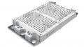
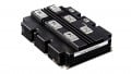
Figure 2. New Package for High Power Modules nHPD2 (new High-Power Density Dual) from Hitachi. Image used courtesy of Bodo’s Power Systems
Simultaneously with the introduction and development of the new semiconductor technology, significant efforts were made to develop the advanced package and interconnect technologies which resulted in a new concept of a new package form factor for high voltage devices. This advanced package began mass production manufacturing under various names by major suppliers of power modules after 2014 - nHPD2 at Hitachi [3] (shown in Figure 2), LinPAK at ABB, XHP 2 and 3 at Infineon, LV100 at Mitsubishi and others.
The result of these development trends leads to possibility where the world’s leading suppliers of power modules currently offer in voltage classes 1700 V and 3300 V all three types of semiconductor modules - Si IGBT, Hybrid Si IGBT / SiC SBD and Full - SiC MOSFET modules, in the same advanced package (except 3300 V Hybrid module). For manufacturers of power converters for traction drives, this is an unusual situation where they can choose the optimal types of power modules that will fulfil the requirements for their specific traction applications.
Requirements and Analysis
In this section, three typical applications from the field of light traction vehicles were selected and operating conditions were specified for them. Furthermore, suitable types of Si IGBT, Hybrid Si IGBT / SiC SBD and Full - SiC power modules were selected for these applications with regard to the requirements of traction converters powered from 750 V DC and also 1500 V DC.
Application No. 1: The application considered here was the main propulsion inverters for trolleybuses and trams
Topology: 2 – Level 3 – Phase Inverter supplying 160 – 210 kW AC induction motor
|
VDC_Link (V) |
VOUT(RMS) (V) |
IOUT(RMS) (A) |
cos (Phi) |
Fsw (kHz) |
fOUT (Hz) |
TA* (°C) |
RthHS** (K/kW) |
| 450 | 420 | 350 | 0.83 | ≥ 2 | 50 | 40 | 20 |
* maximum air ambient temperature
** thermal resistance of heatsink per 1 module
Table 1. Application No 1 conditions applied for simulations.
Analysis and simulations will be performed for the following types of 1700 V modules:
MBM1000FS17G [4]
MBM1000FS17G2-C [4]
MSM900FS17ALT [4]
Application No. 2: The application considered here was the main propulsion inverters for 750 V DC metro vehicles
Topology: 2 – Level 3 – Phase Inverter supplying 2 AC induction motor (2 x 180 kW)
|
VDC_Link (V) |
VOUT(RMS) (V) |
IOUT(RMS) (A) |
cos (Phi) |
Fsw (kHz) |
fOUT (Hz) |
TA* (° C) |
TthHS** (K/kW) |
| 750 |
520 (motor) 672 (breaking) |
465 |
0.86 -0.90 |
≥ 2.5 | 120 | 55 | 15 |
* water temperature
** thermal resistance of heatsink per 1 module
Table 2. Application No 2 conditions applied for simulations.
Analysis and simulations will be performed for the following types of 1700 V modules:
MBM1000FS17G [4]
MBM1000FS17G2-C [4]
MSM900FS17ALT [4]
Application No. 3: The application considered here are the main propulsion inverters for 1500 V DC metro vehicles
Topology: 2 – Level 3 – Phase Inverter supplying 4 AC induction motor (4 x 190 kW)
|
VDC_Link (V) |
VOUT(RMS) (V) |
IOUT(RMS) (A) |
cos (Phi) |
Fsw (kHz) |
fOUT (Hz) |
TA* (° C) |
RthHS (K/kW) |
| 1500 |
1060 (motor) 1340 (breaking) |
490 |
0.85 -0.90 |
>500 | 100 | 40 |
60** 45 *** |
* maximum air ambient temperature
** thermal resistance of heatsink per 1 module for MBM450FS33F
*** thermal resistance of heatsink per 1 module for MBN1200F33F-C3
Table 3. Application No 3 conditions applied for simulations.
Analysis and simulations will be performed for the following types of 3300 V modules: 3 x par.
MBM450FS33F [4] 2 x par.
MBN1200F33F-C3 [4] 2 x par.
MSM800FS33ALT [4]
Loss and temperature calculations will be performed for a range of switching frequencies in order to evaluate the benefits of using Hybrid Si IGBT / SiC SBD or Full - SiC MOSFET modules compared to previously dominant Si IGBT modules.
Simulation Results
In this section, calculations of power losses and junction temperature of selected 1700 V and 3300 V modules in typical applications (main propulsion inverters for trolleybuses, trams and metro cars) are performed by simulation using PLECS simulation tool. In particular, the influence of the required switching frequency of individual applications on the total power losses of the inverter is discussed.
Calculations are performed for operating conditions corresponding to today’s typical traction drives, outlined in the previous section.
All types of power modules compared here have a maximum junction temperature of 150 °C, so we have chosen in the simulations 135 °C as the maximum junction temperature on transistor or diode chip with regard to sufficient lifetime under cyclic loading. The switching frequency was gradually increased until the value when the maximum junction temperature in the each of the module reached the selected limited value.
The simulation results are shown in the form of the dependence of the maximum junction temperature of the used power modules and the efficiency of the inverter on the switching frequency in Figures 3 to 5.


Figure 3. Dependence of maximum junction temperature and inverter efficiency on switching frequency for Application No 1. Image used courtesy of Bodo’s Power Systems


Figure 4. Dependence of maximum junction temperature and inverter efficiency on switching frequency for Application No 2. Image used courtesy of Bodo’s Power Systems
Evaluation of Results and Determination of Recommendations
In this section, based on the results of simulations (total power losses, junction temperatures, and heatsink size), an evaluation of the benefits of using Hybrid Si IGBT / SiC SBD or Full - SiC MOSFET modules is performed compared to the previously dominantly used Si IGBT modules.
Evaluation of the Comparison of 1700 V Power Modules
Results for the application No. 1 show that the maximum usable switching frequency for a Si IGBT module is only slightly higher than 6 kHz, while both the Hybrid Si IGBT / SiC SBD modules and the Full - SiC MOSFET modules can operate with a switching frequency of up to 10 kHz (i.e. with 1.5 x higher). At 7 kHz, the power losses of the whole inverter with Si IGBT modules are 7.8 kW, in the inverter with Hybrid Si IGBT/SiC SBD modules as well as with Full - SiC MOSFET modules the power losses are 4 or 4.1 kW, which is approximately 48 % less. The inverter with Hybrid Si IGBT/SiC SBD modules as well as with Full - SiC MOSFET modules have comparable power losses with the inverter with IGBT modules (at 4 kHz) up to a switching frequency higher than 10 kHz.
Results for the application No. 2 show that the maximum usable switching frequency for a Si IGBT module is only 4 kHz, while both the Hybrid Si IGBT/SiC SBD modules and the Full - SiC MOSFET modules can operate with a switching frequency of up to 6 kHz (i.e. with 1.5 x higher). At 4 kHz, the power losses of the whole inverter with Si IGBT modules are 6.1 kW, in the inverter with Hybrid Si IGBT/ SiC SBD modules as well as with Full - SiC MOSFET modules the power losses are 3.9 or 4.1 kW, which is approximately 33 % less. The inverter with Hybrid Si IGBT/SiC SBD modules as well as with Full - SiC MOSFET modules have comparable power losses with the inverter with IGBT modules (at 3 kHz) up to a switching frequency higher than 6 kHz.
Since all the modules to be compared are in the same housings, a very compact inverter can be implemented.
In applications with current types of traction AC induction motors, the use of fast switching devices can bring some benefits (such as reduced additional motor losses caused by higher harmonics, lower torque pulsation and better control dynamics), but due to some negative effects (such as higher voltage stress on motor windings and bearing currents caused to higher values dv / dt) a significant increase in switching frequency does not make sense.
It is more propriate to use fast switching devices at switching frequencies comparable to today’s IGBT modules, i.e. 2-3 kHz. Thanks to significantly lower power losses in the inverter, efficiency is increased and thus the energy consumption of the whole traction drive is reduced. Increasing the efficiency of the traction inverter is also very important for modern applications of so-called hybrid vehicles, which implement part of their driving cycle powered by traction batteries.
The situation in traction drives with a permanent magnet synchronous motor (PMSM) is somewhat different, which is a new trend in the last few years. For optimal design of traction PMSM, it is very suitable to have an inverter that can operate with a significantly higher switching frequency than the one with IGBT modules. The use of Hybrid Si IGBT/SiC SBD or Full - SiC MOSFET modules in these modern drives is therefore very suitable and advantageous, because in terms of system costs of the whole traction drive (inverter + PMSM), the higher costs of Full - SiC MOSFET modules are largely compensated.
In this particular application, the Hybrid Si IGBT/SiC SBD module achieves the same high performance as the Full - SiC MOSFET module, but its costs are significantly lower. It follows that the mentioned Hybrid module is from the point of view of technical - economic aspects the most suitable candidate for the realization of high efficiency and compact traction inverter for PMSM.
Evaluation of the Comparison of 3300 V Power Modules
Results for the application No. 3 show that the maximum usable switching frequency for a Si IGBT module is only slightly higher than 1 kHz, while both the Hybrid Si IGBT / SiC SBD modules and the Full - SiC MOSFET modules can operate with a switching frequency of up to 3 kHz (i.e. with 3 x higher). At 1 kHz, the power losses of the whole inverter with Si IGBT modules are 23.4 kW, in the inverter with Hybrid Si IGBT/SiC SBD modules as well as with Full - SiC MOSFET modules the power losses are 11,6 or 5,4 kW, which is 50 to 77% less. The inverter with Hybrid Si IGBT/SiC SBD modules and has comparable power losses with the inverter with IGBT modules (at 1 kHz) up to a switching frequency 2,5 kHz as well as with Full - SiC MOSFET modules up to a switching frequency slightly higher than 3 kHz.
It should be noted here that the Hybrid module MBN1200F33F-C3 has a different topology (Single switch) and industry standard larger housing (IHM 140 mm x 130 mm) than the Si IGBT module and the Full - SiC MOSFET module (halfbridge in nHPD2 which is 100 mm x 140 mm). The inverter with these modules achieves similarly high performance as the one with Full - SiC MOSFET modules (usable switching frequency, junction and heatsink temperatures), but at the cost of twice the number of modules and 2.6 times larger and heavier heatsink. It is therefore not possible to build such a compact traction converter with these modules as with SiC MOSFET modules in an nHPD2 package. In addition, the advantage of the lower cost of hybrid modules over Full - SiC MOSFET modules is negated in this case by the total number of modules.
For applications with current types of traction AC induction motors and traction permanent magnet synchronous motor (PMSM) the conclusions similar to those made in section 4.1 for 1700 V power modules apply. This is especially true for applications with PMSM, because a higher switching frequency is really necessary to design an optimal high voltage motor of this type in this power range.


Figure 5. Dependence of maximum junction temperature and inverter efficiency on switching frequency for Application No 3. Image used courtesy of Bodo’s Power Systems
Impact of SiC on System Cost
During the last few years a significant price decrease of SiC semiconductors has been observed. The break even for inverter systems in the range of several 100kW with SiC inside and reduced passive components compared to standard Silicon solutions with dedicated passive components is more and more feasible. With the advancement of front-end processing technology and improved raw material sources shows promising future for power modules using SiC technology. An example of improved processing technology is the dedicated screening in the Front End Factory from Hitachi there is no need to apply an additional Schottky Barrier Diode with the SiC MOSFET. The screening will detect 100 % of possible stacking failures in the raw material. This increases the available area for the SiC chips on the substrate and reduces the cost. This will result in further reduced system costs beside the well-established technical performance. Horowitz et al. [5] demonstrated, through a bottoms-up model that the savings from space and cooling in a SiC-based 1-MW variable-frequency drive resulted in an overall drive cost similar to the current industry standards. We believe the traction applications presented here will have similar overall system cost with SiC power modules.
Conclusions
It is very well known within the industry now that biggest advantages of IGBT modules for the assessed traction conditions are the wide availability of suitable types with sufficient current capacity, low conductivity losses, sufficient short-circuit resistance and reasonable prices. However, with this comes the biggest disadvantage of having a strongly temperature dependent switching losses, which limit the use of higher switching frequencies for these applications. This has been suitably demonstrated with the three application case studies presented here.
From the results presented in this study we can observe that the implementation of Full - SiC MOSFET modules result in significantly lower power losses at similar operating switching frequency of Si IGBT modules. The other perspective would be to have power losses similar to Si IGBT modules but then the operating switching frequency would be significantly higher. The disadvantages are low short circuit withstand capability and at present significantly higher prices compared to similar Si IGBT modules. With applications which have higher DC voltage requirements of 1500 V the implementation of the SiC MOSFET modules is critical to achieve higher switching frequencies and compact inverter sizes.
The use of Hybrid Si IGBT / SiC SBD modules offers a certain compromise between Si IGBT and Full - SiC MOSFET modules in terms of the achieved technical parameters and costs. Their advantage over Si IGBT modules are identically low conductivity losses, but lower switching losses, which will allow either an increase in switching frequency or a reduction in cooling requirements. Compared to Full - SiC MOSFET modules, they have higher short circuit withstand capability and especially lower costs. Overall, with these application case studies we have been able to demonstrate that the use of Si IGBT hybrid power module has suitability in applications for DC link voltage range of 750 V. These power modules need to be assembled in a low inductance package to have the benefit of higher switching frequency.
This article originally appeared in Bodo’s Power Systems magazine.