Facebook
 Google
 GitHub
 Linkedin
ATEX and the Power Management of Smart Gas Meters
This article features Texas Instrument on how the TPS62840 step-down converter in the DGR package can help system and equipment design teams meet aspects of the ATEX Directive and achieve battery lifetime goals.
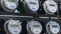
Smart meters have become very reliable and practical in the last decade. As their increasing ability to provide real-time data monitoring, advanced alarms and remote operation led to greater global demand, so too arose an equivalent demand for ultra-low-power electronics.
Smart meters need to keep their power-consumption levels as low as possible, but that poses a challenge for electronics suppliers. For example, one requirement for smart gas meters is 10 years of battery life. Smart meters are also expected to reliably function in extreme environments and weather conditions. Gas meters function in an explosive atmosphere, so they must include protections to operate safely. ATEX, derived from the French phrase “ATmosphère Explosive,” is another name for European Directive 2014/34/EU, which aims to regulate explosion protection in industries that have explosive environments. In this article, I’ll explain how the TPS62840 step-down converter in the DGR package [1] can help system and equipment design teams meet aspects of the ATEX Directive [2] and achieve battery lifetime goals.
ATEX certification
The ATEX certification ATEX is a European Union directive for standardization that covers “equipment and protective systems intended for use in potentially explosive atmospheres.” [2] Explosive atmospheres may occur when flammable gases, vapors, mists or even dust mixed with air accumulate. The ATEX certification aims to minimize or completely eliminate the risk of ignition in such atmospheres and to limit harmful effects in case of an explosion. Explosive atmospheres are present in various industries.
Gases and Liquids
In the chemical industry, chemical processes may create explosive mixtures of combustible gases and liquids. Gas suppliers inherently operate in a potentially explosive environment because gas is flammable. Wood processing companies, waste management companies, energy production companies, and refineries also operate partially or fully in environments with explosion hazards. These industries use a lot of electrical and mechanical equipment and the safety of their operation in such environments is always a concern.
Equipment Groups and Categories Within ATEX
There are different equipment groups and categories within ATEX — depending on the environment, the nature of the explosive atmosphere and the frequency of its occurrence. Table 1 lists the classification of explosive atmospheres caused by mixtures of air and gases, vapors or mists. Residential smart gas meters usually fall in Category 3, Zone 2 in the last row of the table.
Table 1: Classification of different zones for explosive environments [2]
| Category | Zone G (gas) |
Explosive Atmosphere |
Frequency |
| 1 | 0 | Intended for use in areas with explosive atmospheres caused by mixtures of air and gases, vapors or mists | Continuously - for long periods or frequently |
| 2 | 1 | Likely to occur occasionally | |
| 3 | 2 | Unlikely to occur or, if they do occur, likely to do so infrequently and only for a short period |
Although ATEX is European and not harmonized with equivalent American, Canadian or Asian standards, many aspects of the standards are very similar. Let’s review the ATEX intrinsic safety requirements for power-management integrated circuits (ICs) in residential gas meters, along with what you have to consider when designing an IC for this application.
How can power design engineers achieve ATEX certification in residential gas meters?
In order to reduce explosive hazards, the ATEX standard considers ignition sources as the most important factor. For power-management ICs, ignition sources are usually:
- Electric sparks. The amount of electric energy content of the spark determines its risk as an ignition source.
- High surface temperatures.
- Electrostatic discharge, which causes electric sparks and a sudden increase in temperature.
The probability of any of these three events occurring has to be limited or eliminated to ensure safety. The IC package choice for an ATEX-compliant device is the most important contributor in controlling ignition sources. In general, the parameters that reduce such ignition risks are the IC package’s power dissipation capability and its electrical pinout.
Package Power Dissipation Capability
Electronic device development has been moving toward smaller and more integrated and compact designs; so have IC packages. These smaller packages pose a challenge when it comes to thermal management, however, especially at high loads. Whereas a quad flat no-lead package (QFN) and a wafer chip-scale package (WCSP) is more suitable for applications where solution size is a priority, larger packages achieve superior thermal performance and keep device temperatures relatively low, even at high loads.
A high thermal performance very-thin shrink small-outline package (HVSSOP) is a thermally enhanced package with an exposed pad soldered directly to the printed circuit board (PCB). The exposed pad increases the power dissipation capability as much as 1.5 times over standard shrink small-outline packages (SSOP) and thus reduces the device’s operating temperature. A lower self-temperature rise also enables a higher range of ambient temperatures.
Figure 1 shows how an HVSSOP device dissipates around 80% of its heat through the exposed pad, with the help of the thermal vias below it. The rest of the heat mainly dissipates through its leads to the ambient environment. [3]

Figure 1: The power dissipation of an HVSSOP device
Figure 2 shows a thermal image of the TPS62840 in the HVSSOP operating at a 25°C ambient temperature, with an input voltage (VIN) of 6.5 V and an output voltage (VOUT) of 3.6 V at a load (ILOAD) of 750 mA, which is the full load of the device. The device maintains a maximum temperature of 30.1°C while the inductor has a maximum temperature of 32.7°C. These are less than 10°C temperature rises.

Figure 2: A thermal image of the device at a full load
Package Electrical Pinout
In addition to the excellent thermal performance, the electrical pinout and the structure of the package leads are also important. The HVSSOP has a big pitch and thin leads, which enables greater distances between each lead and adjacent leads, and eventually between their

Figure 3: The HVSSOP dimensions

Figure 4: The HVSSOP’s PCB land pattern
PCB land patterns. Figures 3 and 4 show the package dimensions and its PCB land pattern. You can see that the distance between the pins on the PCB land pattern is about 350 μm. This is suitable for ATEX intrinsic safety protection, which requires more than 300 μm of spacing for zone 2 protection. [2]
Moreover, as shown in Figure 5, the VIN and GND pins are separated by a no-connect pin, which increases their spacing to around 1 mm. This amount of spacing mitigates board-level electromigration risks in humid environments and increases IC reliability.

Figure 5: The pinout of the TPS62840 in the DGR package
Electrical Performance
In addition to ATEX-compliant features, the TPS62840 in the DGR package has an ultra-low quiescent current (IQ) of 60nA, and can prolong the battery life of devices that rely on it for power management by increasing efficiency at light loads. With modern microcontrollers having different modes and load currents that can go very low to reduce energy consumption, the device still maintains the efficiency of 80% at a load of 1 μA, as shown in figure 6. The device also has a wide input voltage range of up to 6.5 V, allowing you to choose different battery technologies (alkaline, lithium-thionyl chloride or lithium-ion) that suit your system best.

Figure 6: The efficiency curve of the device vs. the load current at VOUT = 3.6 V
Conclusion
The increasing adoption of smart water, heat, gas and electricity meters, along with the safety requirements imposed by the ATEX Directive, present challenges for power-management design engineers. A long battery life of 10 years or more, an ATEX-compliant IC and very efficient performance at different load profiles are a few requirements that this market needs. With its package’s power dissipation capability and electrical pinout, as well as an extremely low 60 nA IQ, the TPS62840 in the DGR package meets the needs of smart meters and other ultra-low-power systems.
References
- TPS62840 1.8-V to 6.5-V, 750-mA, 60-nA IQ Step-Down Converter. Texas Instruments datasheet, August 2019.
- ATEX–European Directive 2014/34/EU.
- Steven Kummerl. “PowerPAD™ Thermally Enhanced Package.” Texas Instruments application report SLMA002H, July 2018.