Facebook
 Google
 GitHub
 Linkedin
7th Generation 1700 V IGBT Modules: Loss Reduction and Excellent System Performance
This article features Mitsubishi Electric Europe B.V. 7th Generation IGBT Modules with the analysis of IGBT chip and diode chip performances.
For power electronic systems like industrial drives and converters for renewable energy applications, the major system requirements are high reliability, high efficiency, high power density, and competitive costs. In order to meet these requirements, power loss reduction is a key factor. Power loss reduction enables designs with higher power densities and lower IGBT junction temperatures. As a result, higher reliability can be achieved and the cooling system can be accordingly optimized. Therefore, Mitsubishi Electric has developed the new 1.7kV 7th generation IGBT modules with improved performance.
Power module performance affects the overall efficiency of the power electronic system. Accordingly, power modules have to be carefully chosen for a given application depending on various electrical and thermal performance parameters. Mitsubishi Electric had launched the latest 7th generation industrial IGBT modules in the 650V and 1200V classes [1]. These modules have already been well accepted by the market due to the advantages with regards to the key system requirements: high power density, high efficiency, and high reliability. Subsequently, the 1700V IGBT modules were developed to support applications with system voltages of 690Vac.
For renewable applications, the AC-grid filter size can be reduced by increasing the IGBT switching frequency. In the case of motor drives, higher switching frequencies are considered beneficial especially for operation at high output frequencies. Unfortunately, the switching loss behavior of the existing 1700V modules available at the market has not encouraged the designers to explore the possibility of increasing the switching frequency for availing system-level benefits. In order to enable operation at reasonable switching frequencies (above 1000 Hz) with the 1.7kV IGBT modules, the 7th generation IGBT chips and the RFC (Relaxed Field of Cathode) diode chips [2] were developed and optimized for achieving a significant reduction in power loss. An optimized line-up from 100A to 600A current rating has been developed. Further module developments with higher rated currents (up to 1200A) are ongoing.
7th Generation Chip Performance
In order to offer the best electrical characteristics, the latest 7th generation CSTBTTM chip [4] and RFC diode have been used in the 1.7kV IGBT modules. These chips possess an optimized structure and are thinner than previous generation devices. Additionally, the devices have been designed by selecting an appropriate trade-off between the DC performance and the switching performance.
IGBT Chip
The IGBT power loss and the EMI profile has been optimized by designing an optimized MOS structure, advanced termination, and a reduction of the wafer thickness. Figure 1 shows the comparison of the trade-off between VCEsat and Eoff of the 7th generation IGBT with a standard IGBT chip available in the market today. The Eoff of the 7th generation IGBT is approximately 30 percent lower in spite of the same ON-state voltage drop.

Figure 1: Comparison of the trade-off between VCEsat and Eoff
Conditions: VCC=1000 V, IC=600 A, Tj=125 °C, RG min.
Diode Chip
The 7th generation 1.7kV IGBT module is equipped with the RFC diode in order to reduce power loss without generating unnecessary oscillations during switching. The RFC diode has a unique structure in which the P layer is partially added on the cathode side and holes are injected during the recovery period to soften the recovery waveform. Using the RFC structure, it was possible to develop a diode with a reduced wafer thickness and one which does not exhibit snappy behavior. Thus, it was possible to improve the diode trade-off (DC performance versus switching loss). Figure 2 shows the comparison of the trade-off between VF and Err. A significant reduction (about 50%) of recovery losses has been achieved.
Additionally, the lower recovery charge Qrr results in a reduction of IGBT turn-ON switching losses.
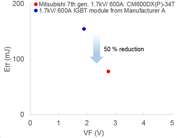
Figure 2: Comparison of the trade-off between VF and ErrConditions: VCC=1000 V, IC=600 A, Tj=125 °C, RG min
Power Loss Comparison
A loss simulation for several application conditions has been performed by using the free simulation software Melcosim [5]. Figure 3 shows the overall power loss comparison of 600A/1700V IGBT module CM600DX(P)-34T [6] with the IGBT module from Manufacturer A. As evident from Figure 3, the power loss of the 7th generation IGBT module is approximately 30 percent lower under typical application conditions (considering a switching frequency of 2kHz). It is clear that a major contributor to the loss improvement is the reduction of diode switching losses and the IGBT switching losses. For a heatsink with Rth(s-a)=90 K/kW, the resulting IGBT-chip temperature Tj is 22K lower at the given application conditions.
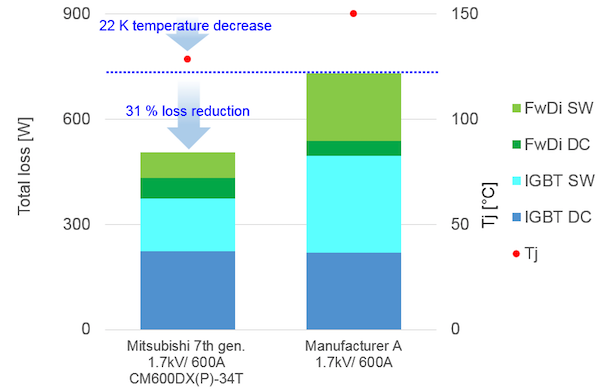
Figure 3: The Power loss comparison of the 600A/1700V IGBT module at 2kHz Conditions: VCC=1000 V, IO=270 A peak, fc=2 kHz, cos(φ)=0.8, M=1, Ta=40 °C, Rth(s-a)=90 K/kW, RG min.
However, if the junction temperature Tj is to be maintained the same, the output current can be increased by approximately 30%. Figure 4 shows the comparison of power loss in the 600A/1700V IGBT module as a function of switching frequency. As evident from Figure 4, the improvement rate is getting higher at a higher frequency. For example, the power loss of the IGBT module from Manufacturer A at 2kHz is almost the same as the overall power loss considering the 7th generation technology’s performance at 4 kHz switching frequency. As a result, by maintaining the same efficiency, the switching frequency could be doubled from 2kHz to 4kHz. This increase in the switching frequency enables a remarkable size and cost reduction of passive components like filter chokes.
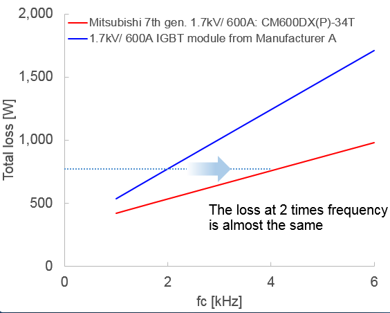
Figure 4: The power loss comparison considering the 600A/1700V IGBT module for several switching frequencies
conditions: VCC=1000 V, IO=270 Apeak, cos(φ)=0.8, M=1, Tj=125 °C, RG min.
Expanded Line-up
In order to meet various application requirements, Mitsubishi Electric has developed a comprehensive modules line-up in 1.7kV class. Table 1 shows the line-up which includes 12 module types in the NX-package ranging from 100 A to 600 A and 6 module types in the standard package ranging from 75A to 400A. In the NX-type package, both solder-pin and press-fit-pin options have been developed for each current rating. They have different terminals. The press-fit-pin package can be assembled by the solderless press process to the PCB board.
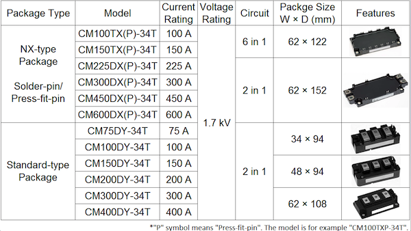
Table 1: Expanded line-up in 1.7 kV class. In the NX-type package, there are two pin types (solder and press-fit) in each current rating.
Furthermore, in the NX-type module, the SLC (Solid Cover) technology delivers an improved thermal cycle capability by combining a resin-insulated metal baseplate and direct potting resin [3]. The advanced SLC technology enables the elimination of the internal bond wires between multiple ceramic substrates which resulting in lower parasitic inductance and higher reliability.
In the standard-type module (refer to Table 1), the TMS (Thick Metal Substrate) technology eliminates the solder layer under the substrate and increases the thermal cycle capability [1]. The parasitic inductance has been reduced by improving the internal layout. In addition, the main terminal pitch for the 62× 108 mm package is 28 mm, which is compatible with the existing package in Europe.
The 7th generation IGBT modules are available with the pre-applied PC-TIM (Phase Change Thermal Interface Material) optionally. It contributes to the simplification of the assembly process and improves the thermal contact between the module base and heatsink.
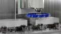
To support applications requiring higher power ratings, a new industrial IGBT module with a half-bridge configuration is under development. This new power module package which is shown in Figure 5 has a dimension of 100x144x40 mm³. IGBT modules based on the 7th generation chip technology, with current ratings up to 1200A in the 1700V category, are under consideration. In case an application requires higher current (more than 1200A) this module is an ideal solution since it is optimized for parallel operation thereby providing a scalable and an efficient solution for high power applications.
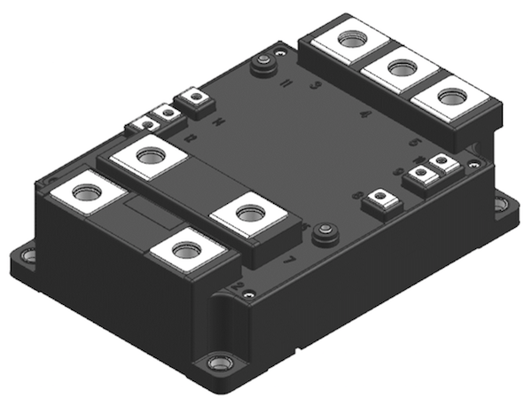
Figure 5: New industrial IGBT module
In the analysis presented here, the IGBT chip performance exhibits approximately 30% improved trade-off between the VCEsat and Eoff. The diode chip performance exhibits 50% lower Err. By utilizing these devices, the overall power loss is approximately 30% lower and Tj is 22K lower than the performance of the IGBT module from Manufacturer A at 2kHz and even more significant in case of higher switching frequencies. This enables either 30% higher output power or doubling the switching frequency (cost saving of passive components).
It is evident that Mitsubishi Electric offers several different types of power semiconductor modules (18 types of module designs) utilizing latest technologies in order to deliver the best system performance and the highest system reliability in the 1700V category.
About the Authors
Masaomi Miyazawa works at Mitsubishi Electric Corporation - Power Device WOrks located in Fukuoka, Japan.
Thomas Radke is a Senior Application Engineer at Mitsubishi Electric Europe B.V, a company branch of Mitsubishi Corporation that focuses on electronics and electrical equipment manufacturing located in Ratingen, Germany. He earned his Bachelor's degree in Electrical Engineering and Electronics at Fachhochschule Düsseldorf (University of Applied Sciences - Dusseldorf). He also acquired his diploma in Associate Engineer in Automation Technology at Siemens Technology Academy - Düsseldorf.
Narender Lakshmanan works as an Application Engineer at Mitsubishi Electric Europe B.V, Ratingen, Germany. He is responsible for power semiconductor-based power converter solutions and has past roles which include project management of EPC projects. He earned his Bachelor's Degree in Electrical Engineer at Anna University, Chennai, Tamil Nadu, India. He then acquired his Master's degree in Electrical Power Engineering at RWTH Aachen University, Aachen, Germany.
References
- M. Miyazawa et al., “7th Generation IGBT Module for Industrial Applications“, PCIM Europe 2014, Nuremberg, Germany, pp. 34-38.
- K. Nakamura et al., “Evaluation of Oscillatory Phenomena in Reverse Operation for High Voltage Diodes”, ISPSD 2009, Barcelona, Spain, pp. 156-159.
- T. Radke et al., “Enhanced Power Density and Expanded Line-up of the 7th Gen. Industrial IGBT Modules Utilizing the Improved Thermal Conductivity of Highly Reliable SLC-Technology”, Bodo’s Power Systems, June 2016, pp. 16-22.
- H. Takahashi et al., ”Carrier Stored Trench-Gate Bipolar Transistor (CSTBT) – A Novel Power Device for High Voltage Application”, ISPSD 1996, Maui, USA, pp. 349-352.
- Melcosim Simulation software “www.mitsubishielectric.com/semi-conductors/simulator/index.html”
- DatasheetCM600DX(P)-34T www.mitsubishielectric.com/semi-conductors/php/oPartProfile.php?FILENAME...
This article originally appeared in the Bodo’s Power Systems magazine.