Facebook
 Google
 GitHub
 Linkedin
7th Gen NX Type Converter Inverter Brake Modules
Applications such as elevator drives or servomotors have several special requirements. One on hand, high efficiency is important, while on the other hand,
Applications such as elevator drives or servomotors have several special requirements. One on hand, high efficiency is important, while on the other hand, the inverter unit is resilient to the different types of load cycling. Furthermore, the inverter must be designed as compact as possible. NX7 CIB modules aim to address these challenges.
Advanced Chip Technology Combined with a New Packaging Concept
Each CIB module consists of an integrated 3 phase inverter part, a converter (3 ph diode rectifier) part and a brake chopper part. The line-up of the latest NX7 CIB modules is shown in Figure 1. The NX7 CIB modules utilize the latest 7th generation CSTBTTM IGBT along with the RFC (Relaxed Field of Cathode) diodes. The electrical characteristics of the new thin wafer 7th generation chips have been tuned for the reduction of overall power losses.
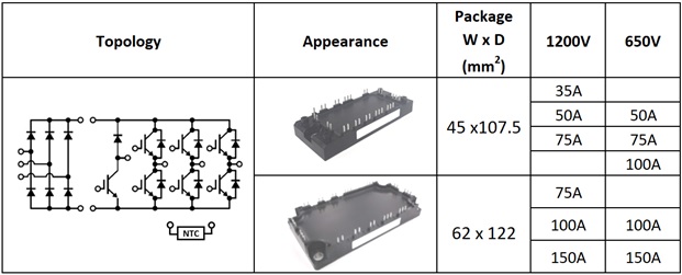
Figure 1: Line-up of the NX7 CIB Modules. NOTE: Pressfit and PCTIM options available.
The NX7 CIB employs a new packaging concept – the SLC (SoLid Cover) Technology which includes an insulated metal baseplate structure (refer to Figure 2). The conventional baseplate has been replaced by an insulated metal baseplate structure where the metal baseplate contains an organic insulation layer directly bonded to it. Therefore the conventional substrate solder between the metal baseplate and isolation ceramic has been eliminated. The soft silicone gel of the conventional structure is replaced by the hard DP-resin (direct potting resin) [1].

Figure 2: Cross section of the NX7 package versus a conventional module package.
Minimizing Losses and Maximizing Performance
Operating the inverter at elevated switching frequencies helps in reducing the audible noise, hence low loss operation even at high switching frequencies is an important capability for applications such as elevators. In addition, limiting the IGBT chip temperature rise during low rotation speed (low output frequency) operation is a key requirement.
Figure 3 indicates the overall power loss comparison of an NX7 CIB module (CM50MXUA-24T) with a previous 6th generation IGBT module (CM50MXA-24S) considering different switching frequencies and a low output current frequency of fout=5Hz. The benefit in terms of power loss between a conventional module and an NX7 CIB module increases with an increase in switching frequency. This can be attributed to the optimization in the trade-off between the switching losses and the ON state losses in the new 7th generation chip technology. A combination of loss reduction and the low thermal resistance (chip to the case) offered by the 7th generation chip technology ensures that the maximum junction temperature can be reduced by utilizing the NX7 CIB module. The analysis indicated in Figure 3 has been carried out considering a target switching dv⁄dt (max)= 10 kV/µs.
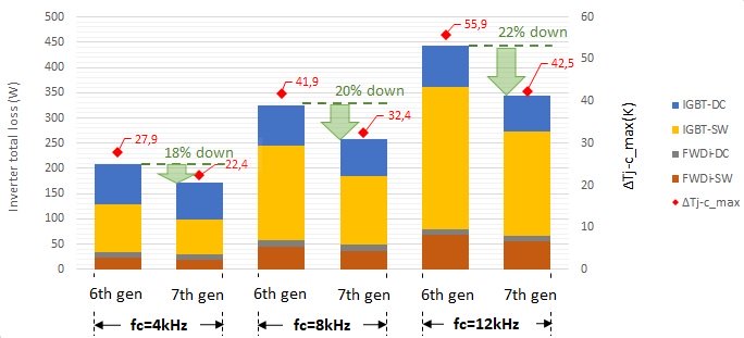
Figure 3: Power loss and junction temperature performance of the NX7 CIB vs conventional module. Conditions: VCC = 600V, Io = 24 Arms, PF = 0.9, M = 1, fout = 5 Hz, Data @ Tj = 125°C.W
Designed for High Reliability
Intermittent operation is a characteristic feature of applications such as elevators. The impact of load cycling can be categorized into two types of cycling phenomena: power cycling and thermal cycling. Power cycling refers to a cycling of the junction temperature which affects the reliability of the chip-tobond wire contact whereas thermal cycling refers to the cycling of baseplate temperature which conventionally affects the solder layer connecting the isolation substrate and the baseplate. But due to the elimination of the ceramic substrate and the solder layer, the limitation pertaining to thermal cycling is not present in NX7 CIB modules.
Case 1: Extended Loading Conditions (Temperature Swing at the Heatsink and Case)
It is common for applications such as elevators to experience operation cycles where the heatsink temperature rises to an allowable point and then falls back to the ambient temperature. The session involving continuous operation which would generate a temperature swing at the heatsink would also involve temperature swings at the case of the power module and at the chip surface (junction). An example of such operation is represented in Figure 4. For this analysis, the Mitsubishi Electric 6th generation modules represent the conventional modules.
The following points are the key conclusions from Figure 4:
- Bottleneck identification: For conventional modules which utilize a baseplate solder layer, thermal cycling performance is the lifetime limitation factor for long operation cycles due to the degradation of the solder layer under such conditions.
- Solution: The bottleneck (solder layer) has been eliminated in the new NX7 module due to the adoption of the IMB structure.
Case 2: Short-term Loading Conditions (Temperature Swing Predominantly at the Chip)
Operating cycles (in the range of a few seconds) which generate temperature swings only at IGBT chip (∆Tj) affect the reliability of the chip to bond wire contact. The amplitude of the ∆Tj is the deciding factor with regards to the power cycling lifetime. This point has been addressed by employing the low loss 7th generation chip technology in combination with the optimized chip to case thermal resistance in the NX7 module. This combination ensures that for the same operating condition, the corresponding ∆Tj is lower (compared the performance of the conventional module). This tendency can be understood from the following results indicating power cycling capability based on the conditions mentioned in Figure 3 (for fc = 12 kHz):
- Conventional CIB (CM50MXA-24S): ∆Tj = 54.52 K: 600 thousand cycles (approx.)
- NX7 CIB (CM50MXUA-24T): ∆Tj = 36.64 K:WWWW 6 million cycles (approx.)

Figure 4: Lifetime estimation for extended duration loading (Conventional module vs NX7 CIB).
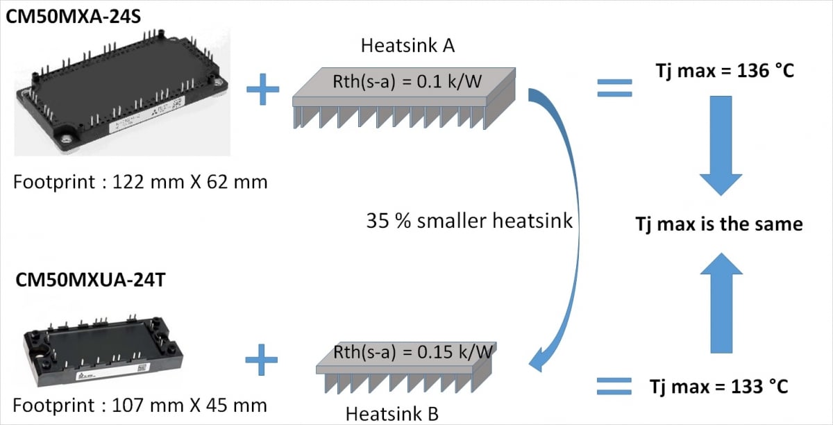
Figure 5: Compactness by heatsink reduction. Conditions: Vcc = 600V, fc = 12 kHz, fout = 5 Hz, M = 1, PF = 0.9, Ic = 24 Arms, Ta = 30 °C, data @ Tj = 125 °C
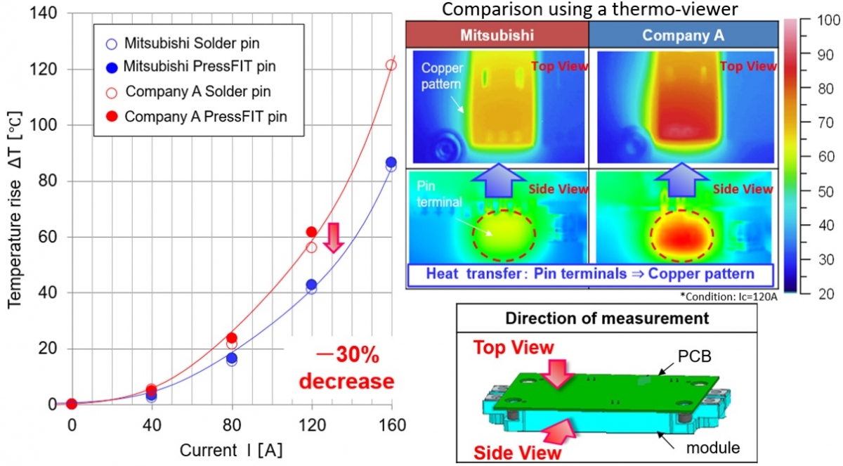
Figure 6: Optimization of terminal temperature in the NX7 CIB module.
Summary of Overall Lifetime Enhancement
Overall improvement in a lifetime has been ensured by the following two-step strategy:
- Elimination of the thermal cycling bottleneck
- Reduction of ∆Tj to achieve better power cycling capability
Compact Design
To achieve a compact design, several important considerations have to be made. The following points illustrate the advantage offered by adopting an NX7 CIB module.
- Since the NX7 CIB module exhibits an improved loss performance and superior thermal performance (refer to Figure 4), the designer can shrink the size of the heatsink in order to achieve an overall compact design. The example presented in Figure 5 illustrates a 35% reduction of the heatsink without causing an increase in the maximum junction temperature.
- To achieve compactness, the classical copper busbar structure can be replaced by a PCB which would be connected to the terminals of the power module via press-fit or soldering. The challenge with this approach is that, due to the high current density at the terminal pins, the temperature developed at the terminal could impose a limitation on the maximum operating current. This possibility has been taken into consideration while developing the NX7 CIB and accordingly the pin structure has been designed to reduce the temperature developed at the terminal during operation. As indicated in Figure 6, the temperature rise developed at the terminals of the Mitsubishi module (NX7 CIB) is lower in comparison with a competitor’s design. The improved thermal conductivity of the potting material (DP-resin) versus gel is an added advantage.
Scalable solutions
The NX7 CIB line-up allows the designer to develop platform solutions – one mechanical design for multiple power ratings. For example, (refer Figure 1), in the 1200V category, the 45mm x 107.5mm module is available in 3 different current ratings (35A, 50A and 75A and the 62mm x 122mm module is available in 3 different current ratings (75A, 100A, 150A). This allows the designer to develop one mechanical design for 3 different power levels.
The requirements of applications such as elevator drives have been taken into consideration while developing the NX7 CIB module. The unique combination of the SLC technology packing and the 7th generation chip technology allows the designer to develop an efficient, reliable and a compact inverter that can be used as a platform solution for multiple power levels.
References
- Thomas Radke, et al: Enhanced IGBT Module Power Density Utilizing the Improved Thermal Conductivity of SLCTechnology, Bodo’s Power systems, June 2016
- Thomas Radke, et al : New Horizons in Thermal Cycling Capability Realized with the 7th gen. IGBT module Based on SLC-Technology, Bodo’s Power systems, May 2017
- MELCOSIM: IGBT thermal and loss simulation software, available at www. mitsubishielectric.com/semiconductors/ simulator/