Facebook
 Google
 GitHub
 Linkedin
Tin and Carbon May Create Safer Solid-State Batteries
A tin-carbon buffer layer shows promising results for suppressing dendrite growth in solid-state lithium-metal batteries.
As demand grows for safer batteries with higher energy density, researchers are turning to all-solid-state batteries (ASSBs). Unlike conventional lithium-ion batteries, ASSBs utilize solid electrolytes rather than flammable liquids, mitigating fire risk and enabling lithium-metal anodes with much higher theoretical capacities.
Yet, lithium dendrite formation has obstructed the road to commercial solid-state batteries. These needlelike structures emerge during charging cycles and penetrate the solid electrolyte, eventually short-circuiting the battery.
However, Lawrence Berkeley National Laboratory researchers may offer a practical and scalable solution to this issue: a solid-state battery using a tin-carbon layer.
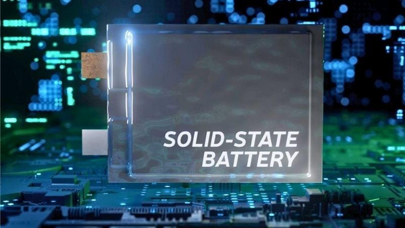
Solid-state battery. Image used courtesy of Adobe Stock
A Dual-Layer Defense
The research, published in ACS Nano, introduces a novel tin-carbon (Sn-C) dual buffer layer deposited on the current collector of an anode-free ASSB, a configuration where the anode forms in situ during the first charge cycle. This method simplifies manufacturing and boosts energy density by eliminating the need for a bulky prefabricated anode.
The team evaluated two variations of the Sn–C structure:
- SUS/Sn/C: Tin is deposited directly on stainless steel, followed by a carbon layer.
- SUS/C/Sn: The order is reversed, with carbon underneath the tin layer.
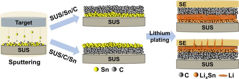
Schematic of tin-carbon dual buffer layer configurations prepared via sputtering. Image used courtesy of Avveru et al.
Through a series of electrochemical and microscopic tests, the SUS/Sn/C structure clearly outperformed its counterpart. This configuration enabled over 450 stable charge/discharge cycles at 1 mA/cm² without short-circuiting, while the SUS/C/Sn version failed within 10 cycles.
Why the Order Matters
Tin, a lithophilic material, facilitates uniform lithium plating. Carbon, by contrast, is lithiophobic and discourages lithium growth toward the solid electrolyte. In the SUS/Sn/C layout, lithium preferentially deposits at the Sn layer (next to the current collector), while the carbon layer on top serves as a physical barrier, preventing dendrite penetration into the solid electrolyte.
This setup enhances uniform lithium deposition and maintains strong interfacial contact between layers, crucial for long-term cycling stability. In contrast, poor adhesion in the SUS/C/Sn design led to non-uniform lithium plating and rapid dendrite formation.
Using in situ optical microscopy, researchers directly observed that the SUS/Sn/C buffer layer promoted the most gradual and uniform expansion at the plating interface, which indicates homogenous lithium growth. Cells using the SUS/Sn/C layer also withstood current densities up to 3 mA/cm² without shorting, underscoring its robustness under demanding conditions.
_vs._SUSCSn_(b)_.jpg)
SUS/Sn/C design (a) vs. SUS/C/Sn (b). Image used courtesy of Avveru et al.
The buffer layers were applied using scalable DC magnetron sputtering techniques, making this approach industrially relevant. The materials (tin and carbon) are also more cost-effective than precious metals like silver used in prior studies with similar objectives.
Toward Safer, Scalable, SSBs
While dendrite suppression is crowded with various approaches, from sacrificial additives to mechanical pressure techniques, the buffer-layer strategy stands out for its simplicity and effectiveness. The research team notes that comparisons across methods remain difficult due to inconsistent industry testing standards, but their approach marks a clear step forward.
Next, the researchers aim to explore more practical full-cell configurations, thinner electrolytes, and longer cycling tests. If successful, this tin-carbon buffer method could help usher in a new generation of safer, lighter, and more powerful lithium batteries.