Facebook
 Google
 GitHub
 Linkedin
DCM™ 1000X Designed to Meet the Future SiC Demand of Electric Vehicle Drive Trains
This article discusses Danfoss' DCM technology for traction applications and its electrical performance.
Global warming, pollution, and international carbon emission targets initiated a process to reduce car emissions. The automotive industry is pushing to improve fuel efficiency and reduce emissions by increasing vehicle electrification. Increasing global demand for BHEV, BEV vehicles, and new drivetrain designs encourages automotive manufacturers to evaluate what constitutes suitable power electronic technology in their current and future designs. Automotive manufacturers constantly seek improved overall performance: higher conversion efficiency, reduced cost, lower weight, and higher power density. Enhancement of energy efficiency reduces the energy expense and battery capacity required to travel a given distance.
Compared to silicon (Si) IGBTs or MOSFETs, silicon carbide (SiC) MOSFETs offer several advantages, i.e., faster-switching capabilities, reducing the losses in the motor and improving the acoustic characteristics of the drive train. By increasing switching frequency, a more sinusoidal motor current can be achieved, thereby reducing motor losses, lowering on-state and switching losses, and increasing thermal conductivity and dielectric strength. Contributing to higher power density and substantially reducing the weight and volume of the inverter.
Utilization of SiC devices to their full capability needs to be evaluated from a system-level since these might introduce challenges for other components in the drive train. For instance, utilizing high switching frequencies without output filters can result in high voltage slope rates (dV/dt), resulting in motor insulation breakdown. Furthermore, higher switching frequencies can cause undesired capacitive couplings and EMI issues.
Perceived high SiC device costs present one of the most obvious arguments against SiC technology adoption. Pricing for SiC chipsets is presently several times higher than Si chipsets. Following the development of previous semiconductor technologies, it is assumed that SiC chipset prices will decrease as increased adoption drives higher fab production capacities and technology advances increase wafer diameters.
Hybrid electric vehicles (HEVs), plug-in hybrid electric vehicles (PHEVs) and battery electric vehicles (BEVs) all contain several critical systems that will benefit from SiC power devices, enhancing both the energy efficiency and performance of electric vehicles.
DCM 1000X
Danfoss extends the DCM 1000 technology platform for traction applications in hybrid electric and battery electric vehicles by introducing the DCM 1000X. The DCM 1000X uses 1200V semiconductors, either in Si or SiC. SiC-based DCM 1000X modules with 1200V blocking voltage are designed for drive trains operating with a DC-link up to 950V with a current rating ranging from 200A-800A. The 1200V platform fulfills all commonly applied insulation requirements, e.g. LV123, IEC 60664-1, or other safety margins for 950V DC-link voltage.
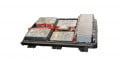
Just like the DCM 1000 (750V), the DCM 1000X is designed to operate under harshest conditions; high-temperature cycles (up to 135K), high humidity, mechanical shock, and vibration. The shock and vibration requirements are addressed using a specific transfer mold package material (Epoxy-Raisin Coating) of the power module, as shown in Figure 1.
To reach maximum power cycle performance and lifetime, the DCM 1000X platform module uses Danfoss Bond Buffer technology (DBB), as does DCM 1000. DBB enables operation at higher junction temperatures. Sintered semiconductors to substrate combined with DBB and copper wire bonding offers higher power and temperature cycling capabilities and up to 15 times higher lifetime than any other standard bonding and joining technology.
Figure 1 also shows that the DCM 1000X uses ShowerPower 3D, a direct-liquid cooling technology which helps to achieve outstanding thermal performance. The SP3D concept offers several benefits compared to other liquid cooling technologies e.g. pin fin coolers.
The parallel cooling principle eliminates temperature gradients associated with the serial cooled pin fin concept. It also allows for tailoring the cooling channels to focus cooling at local hot spots; a feature that is not possible for the pin fin concept due to “shadowing” effects (1).

Figure 1. DCM 1000X
The DCM 1000X is designed and optimized to leverage chip independence. Danfoss Silicon Power can provide DCM 1000X designs based on different semiconductors and thereby ensure an attractive cost base, optimized design, and secure supply.
Electrical Performance DCM 1000X
DCM 1000X fulfills the EV market’s requirement to a nearly double DC-link voltage from 450V to 950V, enabling higher output power and faster-charging capabilities. Efficient 200kW inverter designs or above can be realized by making use of 1200V semiconductors using Si IGBTs or SiC MOSFETs. With higher DC-link voltages, the phase currents can be reduced by 50%, maintain the same output power as an inverter at a lower DC-link voltage, and achieve fast charging times of less than 10 minutes. Since this relation is nonlinear, even higher output power can be achieved using 1200V IGBTs in the DCM 1000X package as compared to the classic 650V/750V power modules with the same footprint.
The benefits of SiC MOSFETs, as introduced above, gives optimal partial load benefits due to the MOSFETs on-state behavior and low switching losses and therefore great overall benefits if higher switching frequencies are utilized by the inverter.
Figure 2 illustrates a comparison between the phase currents of 1200V Si IGBTs/FWDs (1000mm² silicon) and SiC MOSFETs (400 mm² silicon carbide, without external diodes). It is assumed that the coolant boundary conditions for both inverters, 10 liters/minute minimum flow rate and 65°C maximum coolant temperature remain unchanged.
Typical automotive inverter design rules state maximum operating IGBT junction temperature of 165°C for 175°C rated devices, while for SiC MOSFETs, the maximum design operating junction temperature is 190°C for a rated SOA of 200°C. Please note that these temperatures can only be achieved by utilizing DBB®, including a safety margin that is below the maximum operating chip junction temperature.
Furthermore, the ShowerPower 3D cooler enables an unreachable Rth of 0,1K/W at coolant conditions as stated above; this is true for 200mm² total SiC MOSFET area and 300mm² total IGBT area per switch due to the difference in chip size.
This Rth implies, that for a SiC junction temperature of 190°C and a resulting temperature delta of 125K, the total module losses are limited to 2,5kW and the DCM 1000X has the ability to dissipate more than 625W/cm² under peak load and cooling conditions mentioned above (IGBT module losses of 2kW and dissipation of 325W/cm² for the IGBT functions).
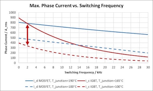
Figure 2. Maximum phase current vs. switching frequency at constant junction temperatures (10K margin to maximum allowable junction temperatures 175°C and 200°C), 850VDC, m=cos(φ)=1, 10l/min. per inverter, 65°C coolant temperature.
In Figure 2, SiC MOSFETs only show a slight decrease of the maximum phase current over switching frequency, demonstrating the great benefit of SiC at high switching frequencies. In other words, the highest IGBT performance without derating is achieved at low switching frequencies. Thus, higher inverter efficiency for the same output power and reasonable switching frequencies can be achieved with SiC MOSFET’s. Comparative efficiency can only be reached by increasing Si area, but the disadvantages will be increased space and increased system cost. In addition, for partial load illustrated at Tjunction = 100°C in Figure 2, the difference between Si and SiC becomes more severe.
Automotive 1200V IGBT traction power modules will remain cost-attractive. Looking deeper at the performance of the DCM 1000X, doubling the DC link voltage and reducing the current by less than 50% point out that the cost driver for SiC is the performance of 1200V IGBT technology as an alternative already enabling a performance step from the 475V towards the 950V DC-link voltage before utilizing SiC MOSFETs.
 .
.
Figure 3: Electrical Performance of the DCM 1000X utilizing latest generation Si 1200V IGBT, 850VDC, m=cos(φ)=1, flow rate given per inverter, 65°C coolant temperature.
As shown in Figure 3, the maximum output current of DCM 1000X utilizing latest generation Si 1200V IGBT is up to 600Arms at 6kHz.
Increasing the switching frequency to 10kHz would reduce phase current by 150Arms due to significant additional switching losses. Due to the well-known on-state characteristic of IGBTs, the partial load efficiency is not optimal.
SiC MOSFETs have been introduced earlier with reduced switching losses and excellent partial load performance. Conduction losses become dominant only at peak loads, requiring an even temperature distribution between the individual chips and a reduction of the Rds(on) temperature gradient.
Figure 4 illustrates the electrical performance of DCM 1000X utilizing the newest generation SiC MOSFETs. The DCM 1000X is currently under development, and users are testing prototypes.

Figure 4. Electrical Performance of the DCM 1000X utilizing latest generation SiC MOSFETs, 850VDC, m=cos(φ)=1, flow rate given per inverter, 65°C coolant temperature.
The performance comparison is carried out at 20kHz and 30kHz at different flow rates. Due to the low influence of the switching frequency and the related losses, the increase from 20kHz to 30kHz leads to a current derating of only 80Arms. The DCM 1000X enables inverter designs up to 600Arms and more, enabling 300kW inverters.
Danfoss is developing an optimized application kit for the DCM 1000X including DC capacitors, busbar connections, a heatsink suitable for 3 half-bridges and gate drivers thus enabling users to evaluate the performance of the DCM 1000X and to support and verify their inverter design.
Summary
The DCM technology platform has been extended to 950V applications, using both Si or SiC chip technology. Future high-performance traction applications will benefit from using this scalable power module platform, offering a full-scale performance and latest Si and SiC semiconductor technology for the best fit to requirements and use.
About the Authors
Omid Shajarati is a product manager for Danfoss Silicon Power. He holds an MSc in electrical engineering - power electronics and drives, a graduate certificate in business administration from Syddansk Universitet, and a graduate diploma in business administration from Syddansk Universitet. He has been at Danfoss since 2002.
Alexander Streibel works at Danfoss Silicon Power as an Application Engineer. He is responsible for automotive and industrial customer's requests; sales support including design, layout and simulation of power module concepts and lifetime requirements; evaluation of upcoming semiconductor technologies and supplier portfolios; investigation about new cooling concepts; silicon carbide power MOSFET packaging; and transfer of knowledge. He is particularly skilled in power electronics, FPGA, and programming. He earned his Bachelor's Degree in Electrical Engineering at Technical University Carolo-Wilhelmina of Braunschweig. He then acquired his Master's Degree in Mechatronics at the University of Southern Denmark located in Odense, Denmark.
Norbert Apfel holds a Master's Degree in Electronic Engineering at the University of Duesseldorf. Norbert currently works as the Head of Global Automotive Sales at Danfoss Silicon Power.
References
- Omid Shajarati, Klaus Olesen, Norbert Apfel, Matthias Beck; DCM™ 1000 Designed to meet the future demand of Electric Vehicle Drive Trains. Bodo’s Power Systems, March 2018.
This article originally appeared in the Bodo’s Power Systems magazine.