Power Electronic Capacitors for Harsh Environment Application
This article answers the question as to how to design capacitors for harsh environment applications.
Power electronic device features are mainly driven by the evolution of semiconductors. However, the capacitors needed as AC Sine-wave filters require a not-negligible space, even if polypropylene—well known for the low loss factor up to high frequencies—is used as a dielectric foil. And still, some heat gets generated. So, what's the best approach when designing power electronic capacitors for harsh environments?
Designing Capacitors With Heat in Mind
Design engineers are continually pushed to reduce the volume of devices but are faced with environmental problems. Heat coming from electric losses is a dominant parameter for the expected life of the capacitor (Arrhenius-law). This heat could be evacuated by a fan, but a fan is a moving component that requires maintenance and the components come in contact with the pollution from the varying environmental conditions.
Figure 1. Temperature and Humidity Operating Reference
Harsh Environment Tests and Standards
Today, metalized polypropylene-film capacitors offer an increasing energy density (high CV- product per volume), a temperature range from -40ºC to 100°C, and a long life expectancy in the range of 100,000 hours under DC load and 30,000 hours under AC load (rated values). Most popular is the radial boxed execution for PCB mounting with 2, 4 or 6 wires connection. As we can see, the AC load creates higher stress for the capacitor construction. In addition to the temperature (Arrhenius), humidity—a difficult to define condition over the capacitor's lifetime—can accelerate the aging process. As an answer to these requirements, “Harsh Environment” tests were generated based on normative solutions. These tests include:
- AEC Q-200 and IEC60068-2-67
- 40°C 93% RH 1000 hours Rated Voltage
- 70°C 70% RH 1000 hours Rated Voltage
- 85°C 85% RH 504 hours Rated Voltage
- 85°C 85% RH 1000 hours Derated Voltage
ICEL-SrL THZ Series Capacitors
Here we describe how the company ICEL- SrL, a privately-owned, medium shape capacitor producer founded in 1960 close to Milano, has prepared a solution to this requirement.
Besides the basic knowledge for producing power electronic capacitors, it was necessary to develop:
- Special finishing and protection materials (resin and case material and design)
- Special film metallization and design
- Innovative production processes
- Dedicated production machines and tools
- Proper testing equipment
- Test facilities for environmental stress
Figure 2. Routine test equipment at ICEL factory
The active part of the capacitor, the PPY winding with the metalized electrodes, must to be protected against humidity. Under AC load, electrochemical corrosion phenomena may occur in the presence of humidity. This may cause faster aging of the capacitor because of related relevant main parameters variation, potential body distortion, and an accelerated increase of failure probability. This effect is more present if the energy density is high – a permanent demand coming from the design engineers. The active part of the capacitor is protected against humidity by the resin in its box. Humidity cannot be avoided completely, but the actions performed and proved by ICEL achieved a significant reduction of humidity while also slowing down the penetration time.
The result of this job is the new ICEL THZ Series that, after passing many individual tests, can fulfill the requirements while keeping the cost and the volume under control.
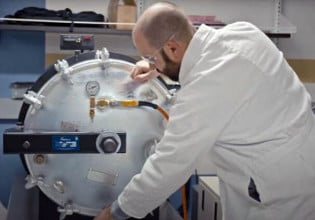
Figure 3. THZ series under approval in ICEL humidity chamber
Standards and Performance Targets for the THZ Series
The new THZ series meets the requirements of IEC61071, IEC60068/1, and RoHS, and REACH.
Temperature Humidity Biased (THB) tests include:
- AEC Q-200-cockpit at Urms; 40°C; 93% RH; 1000 hours
- 70/70/1000 at Urms; 70°C; 70% RH; 1000 hours
- IEC60068-2-67; Cy at Urms; 85°C; 85% RH; 504 hours
- AEC Q-200-85/85/1000 at 0,8xUrms; 85°C; 85% RH; 1000 hours
Performance targets after tests include:
- Change of Capacity < +-10%
- Change of Loss Angle < 2 x initial limit at 1kHz
- Change of Insulation Resistance < 50% of initial limit
- Box swelling < 1/20 of nominal size or < 1mm
About the Authors
Walter Mariani works as the Quality Engineering Manager at ICEL s.r.l since 1986. He is particularly skilled in manufacturing engineering, product development, and process improvement.
Gregor Krauss is the CEO at MUECAP GmbH.
This article originally appeared in the Bodo’s Power Systems magazine.


