Facebook
 Google
 GitHub
 Linkedin
Raspberry Pi Motor Driver Add-on Boards
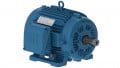
According to Adafruit, the Raspberry Pi is a wonderful little computer, but one thing it isn't very good at is controlling DC Servo Motors - these motors need very specific and repetitive timing pulses to set the position. Instead of asking the Pi Linux kernel to send these signals, Adafruit offers this handy HAT. It adds the capability to control 16 Servos.
In addition to the Adafruit 16-Channel 12-bit PWM/Servo HAT (pictured above), there are numerous other motor driver add-on boards for Raspberry Pi including RoboHAT, a complete robotics controller for your Raspberry Pi based mobile robot, and the Pololu Dual G2 High-Power Motor Driver for Raspberry Pi.
The Adafruit 16-Channel 12-bit PWM/Servo HAT is designed for use with Raspberry Pi Model Zero, A+, B+, Pi 2 or Pi 3 (any Pi with 2x20 header) can be used with the Model A or B if you use a tall 2x13 header instead of the included 2x20.
This Adafruit HAT will drive up to 16 servos or PWM outputs over I2C with only 2 pins. The on-board PWM controller will drive all 16 channels simultaneously with no additional Raspberry Pi processing overhead.
What's more, you can stack up to 62 of them to control up to 992 servos - all with the same 2 pins. Works with any servo that can be powered by 5V and take 3.3V logic level signals.
The drivers have two power supplies. One is VCC - that is the 3.3V power from the Raspberry Pi, it is used to power the PWM chip and determines the I2C logic level and the PWM signal logic level. This supply will always be on if the Pi is plugged in and working, check the PWR LED on the Pi (it's the red LED on the Pi 2, 3. Pi Zero does not have a PWR LED, look for a blinking activity LED)
To power servos you will need to also connect the 5-6V V+ power supply - this is the power supply for the servos. This power supply should be 5 or 6Vdc, most servos work well at 5V and if you give them 6V will be a little stronger.
You can connect this power through the terminal block or the 2.1mm dc jack. There is reverse-polarity protection in case you hook up power backwards.
Best of all, we even have a Python library you can use, so you'll be up and running instantly, to make your robotic creation come to life. The Adafruit PWM/Servo HAT is the perfect solution for any project that requires a lot of servos or PWM outputs.
Each order comes with a Servo HAT, a 2-pin terminal block, four 3x4 headers and a 2x20 socket header. You'll need to do some light through-hole soldering to attach the headers onto the HAT circuit board, but it's easy to do with basic soldering tools like a soldering iron and rosin core electronics solder.
If you would like to stack multiple HATs onto one Pi, you can also pick up a 2x20 stacking header and a set of right-angle 3x4 headers that should be soldered on instead.
This kit does not come with Raspberry Pi, servos, or required 5V power supply. We have recommendations on the required 5-6V power supply on the tutorial page, and a whole bunch of servo options in the Adafruit shop, any 3-pin classic dc hobby servo will work. Also, the terminal blocks included with your product may be blue or black.
Complete Robotics Controller for Raspberry Pi
RoboHAT is a complete robotics controller for your Raspberry Pi based mobile robot.
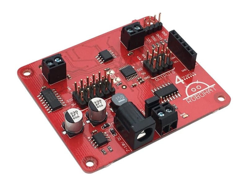
Supports all models of Raspberry Pi with 40 pin Connector: Model A+/B+ as well as Pi 2 and 3 Model B. Programming is fully supported in both Python and Scratch GPIO. Just look at the features provided in this small board:
- Fully HAT specification compliant
- 5V switching regulator to safely power the robot and the Pi from 7V to 10V batteries
- LED indication of 5V power status
- High efficiency, dual H-Bridge driver to drive 2 DC motors (or 2 sets of 2 if using paired motors on each side of the robot)
- 6, 5V level shifted GPIO inputs with GVS 3-pin connectors (Ground, Volts, Signal)
- 4, 5V level shifted GPIO outputs with GVS 3-pin connectors
- 4-pin male header to directly plug in an Ultrasonic distance sensor. Only uses a single pin on the Raspberry Pi GPIO
- Optional separate power for motors (up to 11V and 1.5A per motor)
- The output connectors can be used directly to drive servos
- I2C breakout connector (standard 4tronix I2C port)
- Includes 2 mounting pillars and screws so it can be securely mounted to your Raspberry Pi
- All of this is directly supported in Scratch GPIO 4 onwards - many thanks to Simon Walters for some excellent work
- Python library module and examples freely available
This controller board is supplied fully assembled. No soldering is required.
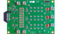
Pololu Dual G2 High-Power Motor Driver for Raspberry Pi
This add-on board makes it easy to control two high-power DC motors with a Raspberry Pi.

Its twin discrete MOSFET H-bridges support a wide operating voltage range and are efficient enough to deliver a continuous current without a heat sink. The drivers offer basic current limiting functionality, and they accept ultrasonic PWM frequencies for quieter operation. The default pin mappings make it easy to get started, but they can be customized for more specialized applications.
These G2 dual high-power motor drivers are add-on boards for the Raspberry Pi, featuring pairs of discrete MOSFET H-bridges designed to drive two large brushed DC motors. They are designed to mount on and plug into compatible Raspberry Pi boards (Model B+ or newer), including the Pi 3 Model B and Model A+. Three versions are available so you can pick the one with the appropriate operating voltage range and output current capabilities for your project.
The minimum operating voltage for all four versions is 6.5V, while the maximum operating voltages are given in the above table. The board also includes an integrated 5V, 2.5A switching step-down regulator that can be used to power the Raspberry Pi it is plugged into, enabling operation from a single power supply.
The driver's default configuration uses six GPIO pins to control the motor drivers, making use of the Raspberry Pi's hardware PWM outputs, and it uses two additional pins to read status outputs from the drivers. However, the pin mappings can be customized if the defaults are not convenient, and pins for current sensing and limiting are accessible on the board for more advanced applications.
Note that this motor driver add-on is designed specifically for newer versions of the Raspberry Pi with 40-pin GPIO headers, including the Model B+, Model A+, Raspberry Pi 2 Model B, and Raspberry Pi 3 Model B.
The board matches the Raspberry Pi HAT (Hardware Attached on Top) mechanical specification, although it does not conform to the full HAT specifications due to the lack of an ID EEPROM. (A footprint for adding your own EEPROM is available for applications where one would be useful; pull-ups on SDA, SCL, and WP are provided.) It is not practical to use this expansion board with the original Raspberry Pi Model A or Model B due to differences in their pinout and form factor.
Features common to all versions:
- PWM operation up to 100kHz
- Motor indicator LEDs show what the outputs are doing even when no motor is connected
- Integrated 5V, 2.5A switching step-down voltage regulator powers the Raspberry Pi base for single-supply operation
- Python library makes it easy to get started using this board as a motor driver expansion board
- GPIO pin mappings can be customized if the default mappings are not convenient
- Current sensing and limiting pins are exposed for advanced use
- Reverse-voltage protection
- Undervoltage shutdown
- Short circuit protection
The following through-hole connectors and mounting hardware are included with the board, which ships with its surface-mount components populated:
- one 2×20-pin 0.1″ female header
- three 2-pin 5mm terminal blocks
- four M2.5 standoffs (11 mm length), screws, and nuts
The 2×20-pin 0.1″ female header should be mounted to the bottom of the board (the side opposite the surface-mount components). Once soldered, this header is used to connect the board to the Raspberry Pi's 40-pin GPIO header. Alternatively, if you want to continue to have access to the Raspberry Pi's 40 GPIO pins while the motor driver board is plugged in, you can install a stackable 2×20-pin female header (not included) instead.
You can solder the terminal blocks to the six large through-holes to make your motor and motor power connections, or you can solder a 0.1″ male header strip (not included) into the smaller through-holes that border these larger holes. Note, however, that the terminal blocks are only rated for 16A, and each header pin pair is only rated for a combined 6A, so for higher-power applications, thick wires should be soldered directly to the board.
The motor driver includes six 100μF or 150μF electrolytic power capacitors, and there is room to add additional capacitors (e.g. to compensate for long power wires or increase stability of the power supply). Additional power capacitors are usually not necessary, and no additional capacitors are included with this motor driver.