Facebook
 Google
 GitHub
 Linkedin
Vishay Introduces a Line of Chip Capacitors With Lead-Bearing Finish Terminations
The new surface-mounted multilayer ceramic chip capacitors are aimed at ameliorating the harmful effects of “tin whiskers”
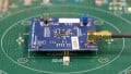
The VJ....32 mounted multilayer ceramic chip (MLCC) series feature tin/lead (PB) termination finishes with minimum 4% lead. They are available in body sizes ranging from 0402 to 1210 with either C0G (NP0) or X7R dielectrics.

Image courtesy of Vishay
The use of lead on the termination finishes, (the part of the electrical contacts on components that make the actual electrical connection with the PCB), can avoid a major problem often described as “whiskers”
What are Whiskers and how Solutions Based on Lead (Pb) Can Protect Against Them?
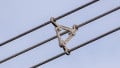
Tin whiskers are electrically conductive growths that can form on the surfaces of components employing tin to make electrical contact with PCBs. What causes whiskers is uncertain, but they often occur in space vehicles.
The problems start when whiskers detach from the component, as they are likely to do. And, as they are electrically conductive, they can cause unintended electrical connections anywhere in the device that the component is part of. Obviously, this can have disastrous effects.
A way to avoid whiskers is to eschew the use of components that are purely tin plated. Its been found that alloying tin with at least 3% Pb will serve to mitigate the formation of whiskers.
Members of the VJ....32 Lead-Bearing Finish MLCCs Series
| Dielectric | Case Code | Maximum Voltage | Capacitance | |
| Minimum | Maximum | |||
| C0G (NP0) | 0402 | 100 | 1.0 pF | 220 pF |
| 0603 | 200 | 1.0 pF | 820 pF | |
| 0805 | 500 | 1.0 pF | 3.9 nF | |
| 1206 | 630 | 1.0 pF | 8.2 nF | |
| 1210 | 630 | 100 pF | 12 nF | |
| X7R | 0402 | 100 | 120 pF | 33 nF |
| 0603 | 200 | 330 pF | 150 nF | |
| 0805 | 200 | 330 pF | 470 nF | |
| 1206 | 630 | 220 pF | 1.0 µF | |
| 1210 | 630 | 390 pF | 1.0 µF | |
Image courtesy of Vishay Datasheet
The same datasheet provides information about the dimensions of the packages, or “case codes,” as well as for an extensive selection guide.
C0G (NP0) Dielectric
Temperature Coefficient of Capacitance (TCC): 0 ppm/°C ±30 ppm/°C from -55 °C to +125 °C
Dissipation Factor (DF):
- 0.1 % maximum at 1.0 VRMS and 1 MHz for values ≤ 1000 pF
- 0.1 % maximum at 1.0 VRMS and 1 kHz for values > 1000 pF
Dielectric Test Strength performed per method 103 of EIA 198-2-E at the following test voltages:
- ≤ 250 VDC-rated: 250% of rated voltage
- 500 VDC-rated: 200% of rated voltage
- 630 VDC-rated: 150% of rated voltage
X7R Dielectric
Temperature Coefficient of Capacitance (TCC): ±15 % from -55 °C to +125 °C, with 0 VDC
applied.
Dissipation Factor (DF):
- 16 V, 25 V ratings: 3.5 % maximum at 1.0 VRMS and 1 kHz
- ratings for greater than 25 V: 2.5 % maximum at 1.0 VRMS and 1 kHz
Dielectric Test Strength performed per method 103 of EIA 198-2-E at the following test voltages:
- ≤250 VDC-rated: 250% of rated voltage
- 500 VDC-rated: minimum 150% of rated voltage
- 630 VDC-rated: minimum 120% of rated voltage
Notes on Use Cases
While members of this series are qualified to AEC-Q200, because of their lead content, they cannot meet RoHS, REACH, or Green requirements, so it is unlikely that they can actually be used for automotive purposes.
These units are appropriate for cheaper, short lived low earth orbit (LEO) space vehicles. Geosynchronous (GEO) satellites and deep space vehicle applications generally call for more extensively tested, far more expensive components than those of this series.
Applications
These units will find application where ameliorating the effects of “tin whiskers” is mandatory.
- Space vehicles
- Low earth orbit (LEO) satellites
- Aerospace applications
- Military
Physical Considerations
The units operate over a temperature range of -55 to +150℃, with changed characteristics above 125℃.