Facebook
 Google
 GitHub
 Linkedin
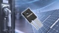
Littelfuse Introduces a Series of 1700V SiC Schottky Barrier Diodes
The new silicon carbide (SiC) diodes feature higher speed and greater efficiency than last generation silicon diodes.
The LSIC2SD170Bxx Series SiC Schottky Diodes are available with forward continuous current ratings of either 10, 25, or 50 amps. The units can withstand high surge currents and feature close-to-zero reverse recovery current.
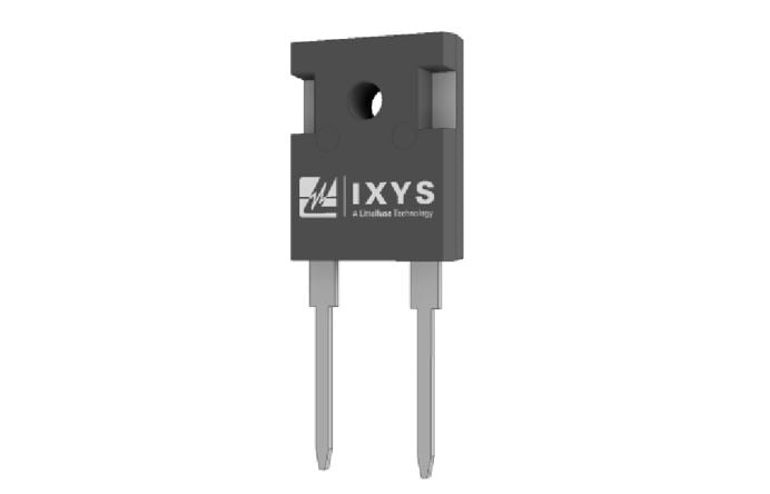
Image courtesy of LSIC2SD170B25 datasheet
The Advantages of SiC Schottky Barrier Diodes
With this new series, Littelfuse extends its offerings of SiC Schottky barrier diodes to the 1700 volt class. When compared to their silicon-based predecessors, the SiC devices offer faster switching speeds. They are also more compact, so they are smaller, or they can handle more power in the same sized package.
The new units offer lower forward voltage for lower switching losses and greater efficiency. The forward voltage also features a positive temperature coefficient, allowing for safer operation and for ease of paralleling.
As described by Francois Perraud, Product Marketing Manager, SiC Products at Littelfuse, "Using SiC diodes in power designs instead of diodes based on legacy silicon-based technology helps designers develop more energy efficient power converters, saving energy and reducing costs related to cooling the power electronics." He goes on to state that,”They enable the design of faster switching power electronics in the converters which can then be made more compact at the same output power or pack more power in the same volume."
Characteristics of the Three Diodes
The devices offer a very fast switching behavior that is independent of temperature. Forward voltage for all three units (typical @ 25℃) is 1.5 volts
For the 10 amp LSIC2SD170B10, the 25 amp LSIC2SD170B25, and the 50 amp LSIC2SD170B50, respectively, the following conditions apply:
- Non-repetitive forward surge currents (see the above datasheets for conditions) are 72 amps, 144 amps, and 280 amps.
- Power dissipations at 25℃ are 176W, 340W, and 650W.
- Thermal resistance, junction to case (maximum) are 0.85°C/W, 0.44°C/W, and 0.23°C/W.
- Reverse current, typical at 25℃, are <1µA, 2µA, and 5µA.
- Total capacitive charges (Qc) are 74nC, 175nC and 353nC.
- Capacitive stored energies (Ec) are (typically) 17µJ, 39µJ, and 77µJ.
Current and Power Derating
The stated forward continuous current ratings for these devices of 10, 25 and 50 amps are for 150℃ with pure DC. Lower duty cycles and lower temperatures allow for more current, as detailed in figure 4 of the three datasheets. In all cases, forward current carrying capacity, as well as power dissipations, derate to zero at a junction temperature of 175℃.
Applications
- Data centers
- EV Charging applications
- Solar Inverters
- Boost diodes in power factor correction (PFC) or DC/DC stages
- Industrial motor drives
- High-speed rectifiers
- Building Automation
- Uninterruptable power supplies
- Industrial switched-mode power supplies (SMPS)
Physical
- Members of the LSIC2SD170Bxx series are available in TO-247-2L packages with maximum dimensions of 16.26 by 21.46 mm
- Cathode is connected to device case
- The units operate over a junction temperature of -55 to 175℃
Regulatory
- AEC-Q101 qualified
Environmental
- Series members are RoHS compatible