Facebook
 Google
 GitHub
 Linkedin
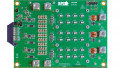
EPC Debuts a Bidirectional, 50W eGaN FET-based Buck-Boost Converter
The new demonstration board operates either as a 12V to 60V boost converter or as a 48V to 12V buck converter.
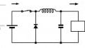
EPC’s EPC9162 is a synchronous converter featuring the company’s fast-switching 100V EPC2052 GaN FETs for reduced switching losses and for high operational efficiency. As this semiconductor is an N-channel MOSFETs used on both the high side and low side, a bootstrap circuit is needed on the high-side, which is implemented through the use of EPC’s EPC2038.

Simplified block diagram for the EPC9162. Modified image courtesy of Quick Start Guide
As delivered, the EPC9162 is default programmed as a boost converter operating at a 12V input, providing an output of as much as 50W at 60V. In the other direction, it can act as a buck converter with an input of 48V delivering 12V at 60 W.
High Levels of Efficiency
The EPC2052s, due to their fast switching capabilities, enable low switching losses and high efficiency. When operating in its boost converter configuration, the unit features a peak and light load efficiencies of 95.3% and 86%, respectively. In buck mode efficiency is cited at 96%
As stated by Alex Lidow, CEO of EPC “In applications where light-load efficiency is critical, such as LED backlighting for laptops and monitors, the low switching losses of eGaN FETs provide high efficiency with very low temperature rise to prevent equipment overheating.” He goes on to state that “The synchronous boost topology is a simple, low-cost solution for power system designers.”
The EPC9162 Demonstration Board is a Direct Guide for Real World Applications
EPC clearly states that the EPC9162 is meant only for evaluation purposes and cannot be directly utilized as a final product. However the company makes it easier for the demonstration board to serve as the genesis of an actual OEM product by providing the Gerber files, a bill of materials and schematics, all available on the EPC website.
Operational Details
The EPC9162 switches at 500kHz. The device is digitally controlled and is reprogrammable. Additionally firmware updates will be provided by EPC if needed.
The demonstration board is intended for use at low ambient temperature for bench evaluation only. There is no facility for cooling, so users must be careful not to exceed the EPC2052’s maximum junction temperature of 150℃. There is also no provision against excessive current.
The demonstration board is driven and controlled by a Microchip dsPIC33CK32MP102
Digital Signal Controller DSC. It does so in a completely digital manner, with feedback loops devised and executed via software.
The EPC2052 eGaN FET
The demonstration board is purposed largely as a vehicle to showcase the EPC2052. This enhancement mode power transistor feature an RDS(ON) of 13.5mΩ. Maximum VDS is 100V continuous, and 120V for up to 10,000 5ms pulses. Maximum drain current is 8.2 amps, or 74A for 300us pulses.
The typical specifications listed below are subject to conditions enumerated in the datasheet.
- Input capacitance: 441pF
- Reverse Transfer Capacitance: 3.2pF
- Output Capacitance: 195pF
- Total Gate Charge: 3.5nC
- Gate to Source Charge: 1.5nC
- Gate to Drain Charge: 0.5nC
- Gate Charge at Threshold: 1.0nC
- Output Charge: 13nC
- Source-Drain Recovery Charge: 0nC
Applications for the EPC2052
- 48 V Servers
- Isolated Power Supplies
- Lidar/Pulsed Power
- Point of Load Converters
- Low Inductance Motor Drive
- LED Lighting
- Class D Audio
Physical considerations
- The EPC2052 is available in a 1.5 x 1.5mm passivated die form with solder bumps
- The device operates over a temperature range of -40 to +150℃
Environment considerations for the EPC2052
- RoHS compliant
- Halogen free
Featured image used courtesy of EPC