Facebook
 Google
 GitHub
 Linkedin
Direct Liquid Cooling Multiplies Power-Cycling Life in Truck Drivetrains
Learn how Littelfuse, Daimler Truck AG, and the Steinbeis Institute validated a non-isolated power module architecture that cuts IGBT junction temperatures by up to 83 K and clears the path to higher power densities.
Commercial electric vehicles pack more electronics into less space than almost any other application on the road. A heavy-duty truck or bus drivetrain inverter is expected to deliver at least 600 kW of continuous output from a power section that has to stay well below 5 dm³, a power-density requirement in the range of 120 kW/dm³. Even at 99% efficiency, that still leaves roughly 6 kW of losses that have to go somewhere.
Liquid cooling is standard equipment on this class of vehicle, so the cooling capacity is there. The limitation lies inside the power module itself.
Why Ceramic Isolation Is the Real Bottleneck
Conventional power modules isolate the semiconductor electrically from the cooling system using a ceramic layer. That layer is necessary for safety, but as a rule of thumb, any material that provides electrical isolation is also a poor thermal conductor. The ceramic that keeps the chip electrically separated from the cold-plate is, at the same time, the biggest obstacle to getting heat out of the chip.
Engineers have chipped away at this problem for years—mounting modules to closed liquid cold-plates, then treating the power device itself as the lid on an open cold-plate, then adding pin-fin or similar surface structures to increase turbulence and contact area on the base plate. Each step helps. None of them removes the ceramic.
Relocating Isolation to the Coolant
The approach behind this work takes a different starting point: instead of isolating the semiconductor from the coolant, why not let the coolant provide the isolation? Littelfuse, working with Daimler Truck AG and the Steinbeis Institute, developed a non-isolated power semiconductor assembly that mounts IGBTs and diodes directly to a liquid cold-plate, using the dielectric properties of the coolant itself as the isolation barrier. That eliminates the ceramic layer and several other layers in the conventional module stack in one step. See Figure 1.
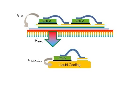
Figure 1. Comparison between a classical isolated module assembly and the non-isolated, direct-liquid-cooled setup. Removing the isolation layer from the stack shortens the thermal path from die to coolant.
A New Interconnection to Match
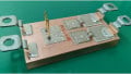
The prototype module built to evaluate the concept uses a single-switch configuration: four paralleled IGBTs rated 1200 V and 150 A each, plus four freewheeling diodes of the same rating. In place of bond wires, the module uses proprietary tab-and-clip interconnection technology shown in Figure 2, which offers a far larger cross-section for current and correspondingly lower resistive losses and lower operating temperature.
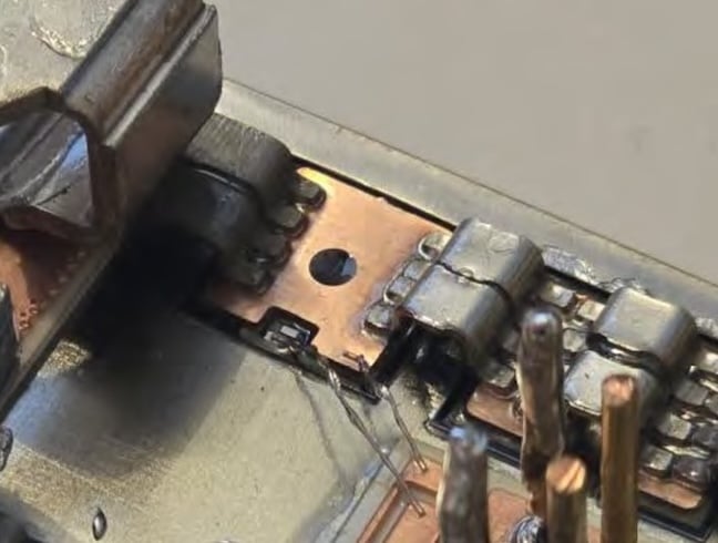
Figure 2. Close-up view of the tab-and-clip interconnection technology, which replaces bond wires in this design.
Thermal and Electrical Validation
Thermal testing, conducted with the device blackened and observed by infrared camera, determined a thermal resistance junction-to-coolant of less than 0.08 K/W—low enough that the module sustained 800 A DC within thermal limits while the cold-plate dissipated close to 1,300 W of losses. A dedicated gate-driver board, built around a non-isolated gate-driver IC with integrated desaturation detection and a charge pump for positive and negative gate voltages, supported double-pulse testing up to 800 V and 160 A to characterize switching losses and transfer characteristics.
Putting It to the Test: A Real Truck Mission Profile
To evaluate performance under realistic operating conditions, the team ran a simulation using data recorded on the mission profile taken from a truck during operation covering close to 700 km of German highway driving with a 40-ton gross vehicle weight. Vehicle speed, motor torque, rotational speed, drivetrain DC current, and DC-link voltage were all recorded and fed into the thermal simulation model. See Figure 3. The most frequently occurring load condition had a peak DC current of about 200 A, and therefore was the relevant point for long-term thermal stress.
Three cooling scenarios were compared at that operating point:
- Classical isolated power modules on a liquid cold-plate
- The new non-isolated design cooled with oil
- The same non-isolated design cooled with a de-ionized water/glycol mixture.
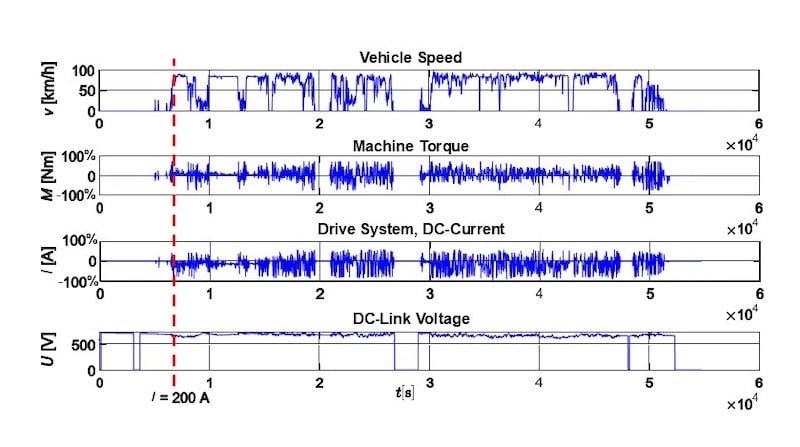
Figure 3. Mission profile recorded on German highways, used as the basis for the thermal simulation.
The Payoff: Temperature, Losses, and Lifetime
Compared to the classical isolated module, the water/glycol-cooled non-isolated design reduced IGBT junction temperature by up to 82.9 K and diode junction temperature by up to 87.8K, while cutting total module losses by roughly 15%.
Lower junction temperature and a smaller temperature swing both significantly increase power-cycling lifetime. Combining the interconnection change with the reduced temperature swing (from roughly 80 K down to 25 K in the simulation), the analysis projects an improvement in power-cycling capability by at least two magnitudes compared to a classical solder-bond, ceramic-isolated design. This improvement moves the design from a lifetime measured in the hundreds of thousands of cycles to one measured in the tens of millions.
“In-depth analysis of the correlation revealed a damage reduction of 97% when comparing the classical approach to the DLC-Module. In turn, the same load profile can be passed through 30 times as often, leading to a similar factor in lifetime.”
For commercial electric vehicles, direct liquid cooling reduces the space required for high-power drivetrain electronics, reduces electronic design complexity, and improves efficiency. Most significantly, the direct cooling technology reduces power semiconductor junction temperature, enhancing lifetime by a large factor and improving reliability. The technology keeps commercial electric vehicles on the road longer.
What Comes Next
The current prototypes are being built into fully functional inverters for lab testing against the full load profile, with on-road testing and dynamometer validation to follow. The direct-cooling and tab-and-clip approach is not limited to silicon IGBTs. The same architecture can be investigated for Si and SiC MOSFETs, and even classical bipolar devices such as thyristors and diodes.
The result breaks with a long-standing belief in power semiconductor design: that isolation is accomplished using ceramics on the device. By shifting that function to the dielectric coolant surrounding the device, the approach removes one of the field’s longest-standing constraints. Efficiency, lifetime, reliability, and reduced material use all improve as a result.
All images used courtesy of Littelfuse.